|
|
 Rank: Vice-Master    Groups: Registered
Joined: 05/04/2013 Posts: 540 Points: 1,630 Location: England
|
Part 1 3D printers have been exciting things to follow for a while now and when I found there were kit versions available to build I thought it would be a great thing to do. Not only can I use a 3D printer to create even more models but it also could serve some more practical purposes as well. My diary was a little delayed by issues with the first pack but thank's to Tomick I am up and running now.  The Table Base The Table BaseThis build starts with the area that the model will be printed on.  We start with the supporting structure that sits under the surface the model is printed on. The structural parts are all transparent acrylic which will mean you can see the printer mechanisms working as it prints a model.  Washers are added to each reinforcing plate to enable them to be attached to the table base.  The reinforcing plates are then screwed onto the table base. I had to be mindful not to screw the screws in too tightly as this could crack the acrylic. 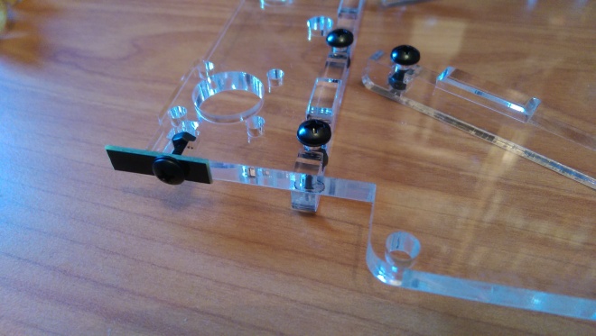 A metal plate which is part of one of the limit switches added at a later part it attached to the side of the table base. 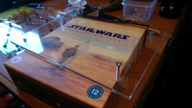 Next The upper section of the table base is prepared to be attached to the lower table base. Screws are screwed into each of the conical holes. 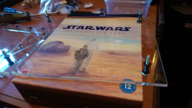 The upper base is then flipped over and a spring between two washers is added to each screw. 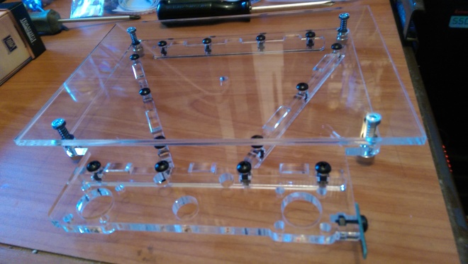 The two table base sections are then attached with nuts.  The nuts can then be tightened to put pressure onto the springs in order to change the alignment of the table base. The Y limit Switch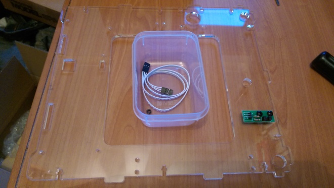 Lastly the right side panel is unwrapped and the y limit switch circuit board is attached to the panel with some screws and nuts. Spacers are used to keep the circuit board away from the acrylic. In 3D printers limit switches are used to determine the point of origin for an axis that the printer moves on. Finished 3D Printer, RB7, Hummer, Skyrider drone & Combat tank collection http://www.model-space.com/gb/
|
|
|
Rank: Vice-Master Groups: Registered
Joined: 05/04/2013 Posts: 540 Points: 1,630 Location: England
|
Part 2 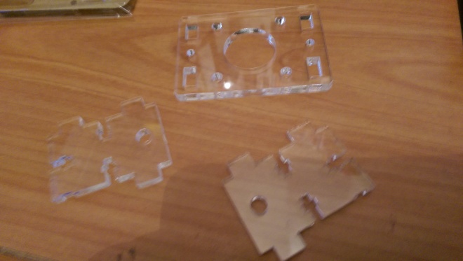 The first thing to do in part 2 is to build the bracket for the printers z axis motor.  This is put together in the same way as the previous acrylic parts<!--more--> by sliding nuts into slots in one panel and attaching the other with screws.  With both sides of the bracket attached it is ready to be fitted to the bottom panel of the printer. 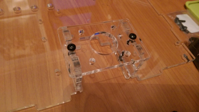 The bracket is attached to the bottom panel in the same way.  Next a noise filter is to be the rear panel. This will filter out electromagnetic noise and be the printers power inlet. 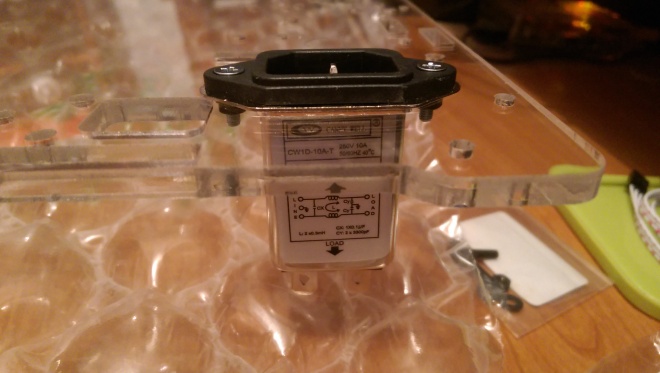 The noise filter is attached to the rear panel of the printer with screws and nuts.  Next a cooling fan needs to be added to the rear panel of the printer. 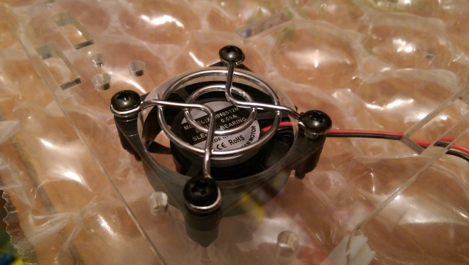 The fans guard is held onto the outside of the panel and screws are fed through the holes in the guard. The fan is then held against the inside of the panel and is secured with nuts. 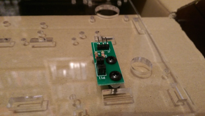 Next the x axis limit switch is added to the rear panel. 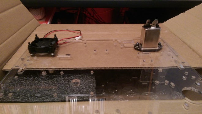 The panels are put away safely for the next stage. This should be due any day now and enable me to put the panels together meaning I will need to find a more permanent home for the the printer. Finished 3D Printer, RB7, Hummer, Skyrider drone & Combat tank collection http://www.model-space.com/gb/
|
|
|
 Rank: Super-Elite     Groups: Registered, Forum Support Team, Administrators, Global Forum Support Team, Moderator, Official Builds Joined: 09/11/2012 Posts: 8,520 Points: 24,651 Location: East midlands
|
|
|
|
 Rank: Pro Groups: Joined: 24/08/2009 Posts: 48,827 Points: -13,348
|
Great to see your finally underway with this build 
|
|
|
Rank: Vice-Master Groups: Registered
Joined: 05/04/2013 Posts: 540 Points: 1,630 Location: England
|
Thanks Tomick I am eagerly awaiting the next pack which should be due any time now. I try to keep things a surprise but I always end up looking at your diary and spoiling it.  I recently been playing around more and more with 3D modelling. There are two reasons for this. Obviously the first reason is that I am building the 3D printer. Secondly I have been prototyping different computer game ideas in Unity for a while now and decided to switch to 3D for some of my ideas. Here is a couple of images of a tank model I am working on. It does not really have a dedicated purpose yet but I thought if I made any models for use in games they could be simplified for printing purposes.  The weapon of choice for my 3D modelling is Blender. This is because it is a free open source application with plenty of tutorials on itself and integration with Unity.  It looks like 3D printing will pose its own challenges where things like over hanging parts will be a challenge. This does give me the idea of printing a model over several runs in kit form though which would be cool. Finished 3D Printer, RB7, Hummer, Skyrider drone & Combat tank collection http://www.model-space.com/gb/
|
|
|
Rank: Super-Elite  Groups: Registered
Joined: 27/01/2014 Posts: 5,060 Points: 14,980
|
Its great to see you finally started Kenjara, looks like you are enjoying it so and having fun so far
|
|
|
Rank: Vice-Master Groups: Registered
Joined: 05/04/2013 Posts: 540 Points: 1,630 Location: England
|
Thanks Dave its been great fun so far, onto pack 3! 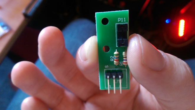 The first stage in part 3 is to fit the Z-axis limit switch to the rear panel.  The rear panel already has a X-axis limit<!--more--> switch on it so there are now two limit switches on here. 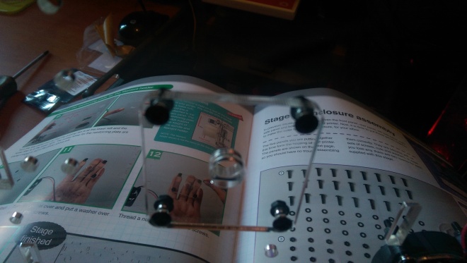 Next a reinforcing plate for the filament spindle as added to the rear panel. The filiment spool will sit on this spindle. This will feed plastic into the 3D printer. <img class="alignnone size-large wp-image-1416" src="https://kenjaraskits.files.wordpress.com/2015/06/imag1049.jpg?w=660[/img] Next the panels are connected to each other. 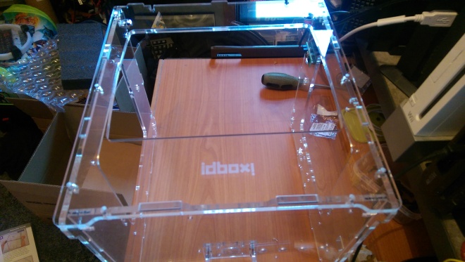 Once a solid structure is formed with 4 of the panels nuts are slid into the nut housings so the that panels can be screwed together.  The screws are hand tightened for now until each side has a panel 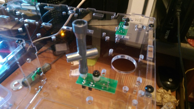 The limit switches are straightened and then tightened fully. 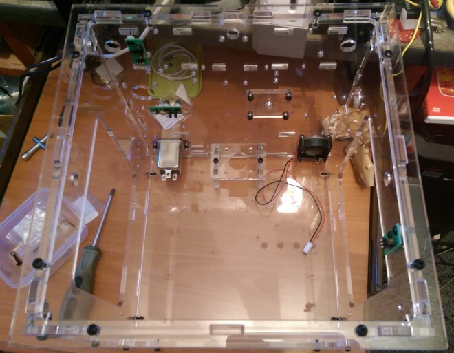 A temporary assembly jig is added as the top panel. This is a hollow panel allowing parts to be fitted while providing a greater rigidity to the case.  With all the panels in place the screws are tightened with a screw driver. 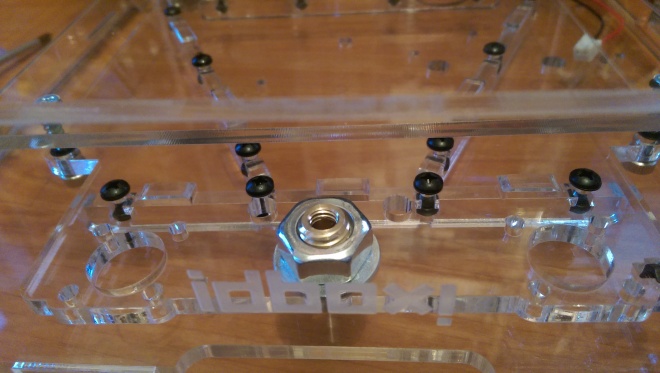 Lastly the lead screw nut is attached to the table base. This nut will be attached to a rod which will turn and raise/lower the table. Finished 3D Printer, RB7, Hummer, Skyrider drone & Combat tank collection http://www.model-space.com/gb/
|
|
|
Rank: Vice-Master Groups: Registered
Joined: 05/04/2013 Posts: 540 Points: 1,630 Location: England
|
I have been doing a little more 3D modelling while waiting for the next pack! I decided to attempt to add some tracks to my tank model I am working on in blender. The tank tracks I am making here are completely useless for 3D Printing purposes. These are for me to animate on the model when playing about with it in games.  To make a set of tracks I have to repeat a mesh through a curve. This was done using a combination of the curve and array modifiers in blender. My first attempts created some major deformations. These were caused by silly mistakes I was making with regard to not centering the origins of my objects properly. The black line in the above image is the curve I have made for the tracks to follow. 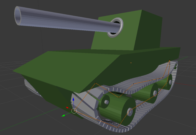 Here you can see the nodes of the curve I made with their links highlighted in orange. At this point the origin of my objects was still off resulting in the deformation you can see on each track link.  With everything corrected my track links flowed nicely along the curve I made. Finished 3D Printer, RB7, Hummer, Skyrider drone & Combat tank collection http://www.model-space.com/gb/
|
|
|
Rank: Vice-Master Groups: Registered
Joined: 05/04/2013 Posts: 540 Points: 1,630 Location: England
|
I decided to have a go at making a basic 3D humanoid in blender. After a little research I gave it ago and I am rather pleased with my initial results.  Here I am using a mirror modifier to create my model. This means everything I do on the left is reflected on the right meaning I only have to create on side of the human. 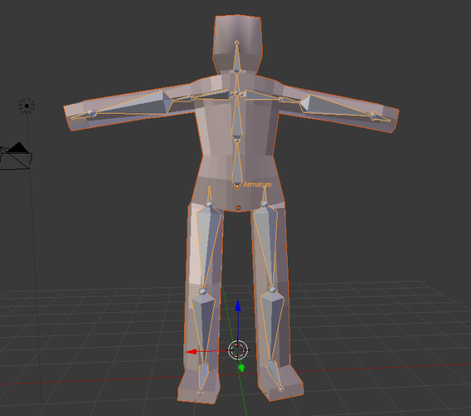 After I was happy with my model I added some bones to it. These enable me to animate the model. By applying rotations to the bones any parts of the model the rotation should affect will also move. This is a bit like black magic to me (I thought animating limbs would be much harder. 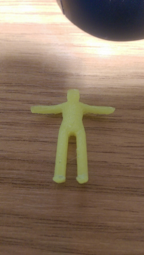 Left in its default pose I exported my model as an stl so that it could be printed. My printer is still a while away from completion so a friend printed it for me. It was really nice to see something I created in blender in physical form. 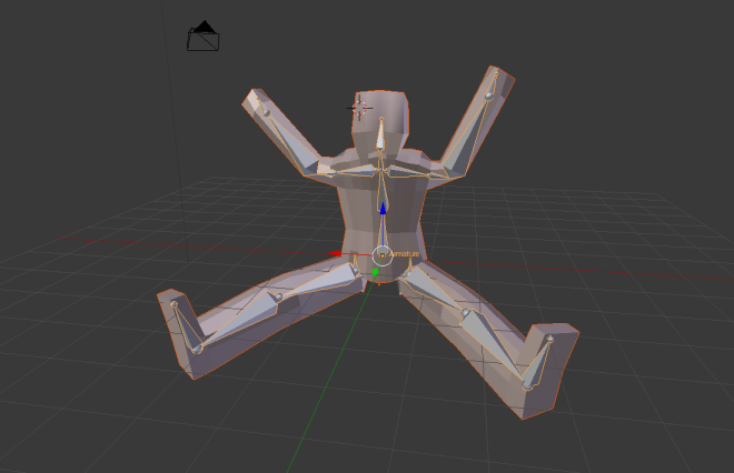 Next I started playing around with posing my model. I decided to give a basic sitting pose a go. 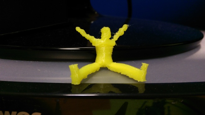 It turned out OK but was a bit harder for the printer to print at this size. With the ease of posing figures in blender I have lots of ideas with regards to printing miniatures like soldiers etc... Exciting time indeed! I hope to have the next stage of my build up soon! Finished 3D Printer, RB7, Hummer, Skyrider drone & Combat tank collection http://www.model-space.com/gb/
|
|
|
Rank: Pro Groups: Joined: 24/08/2009 Posts: 48,827 Points: -13,348
|
Well done for having a go
|
|
|
Rank: Vice-Master Groups: Registered
Joined: 05/04/2013 Posts: 540 Points: 1,630 Location: England
|
Thanks Tom. I will be giving my friend many more creations to try over the coming weeks. I also want to try the 3D package mentioned in the magazine. Pack 4 contains some rods and pulleys for the build. 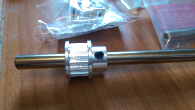 The first step was to put one of the timing pulleys into the left Y-axis rod. 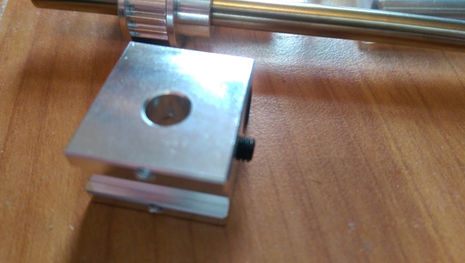 Next a slider is added to rod.  With the slider on the rod a second longer pulley is added to the other end.  Three pulley belts are then added to the rod and the rod is secure into the 3D printers case. A bearing sits at each end of the rod and is held in place with a screw at each end. 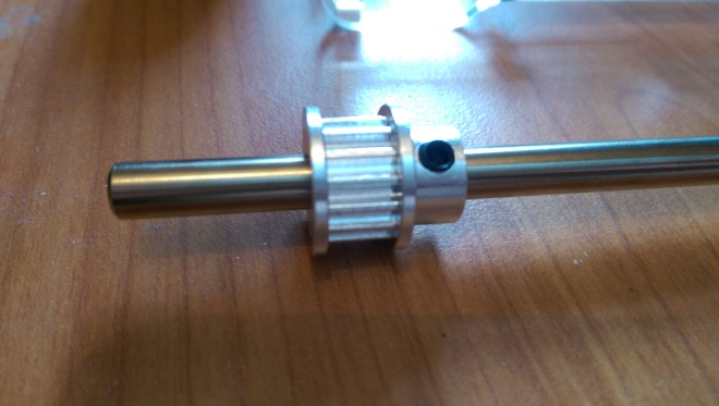 This part ends with the preparation of the right hand y axis rod. I am really enjoying this build so far. It's great to build something like this as you can get to know what every part does and how to fix it. Finished 3D Printer, RB7, Hummer, Skyrider drone & Combat tank collection http://www.model-space.com/gb/
|
|
|
Rank: Vice-Master Groups: Registered
Joined: 05/04/2013 Posts: 540 Points: 1,630 Location: England
|
Its been a while due to some shipment delays but here are the next two 3D Printer packs. Part 5
 In this stage we add some acrylic cogs to the slider rods facing the front of the printer.  Next the rear x axis rod is added to the printer. It is first prepared by adding the pulleys and cogs to the rod.  Part 6 Part 6
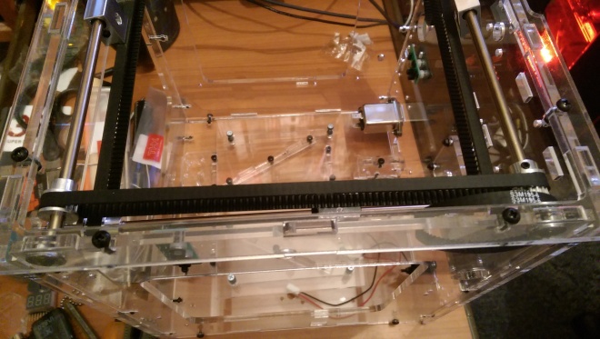 In stage 6 the front x axis slider rod is added. 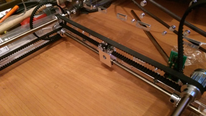 Next belt clamps are added to each of the sliders. The printer is turned upside down to make it easier to add the down facing clamps. 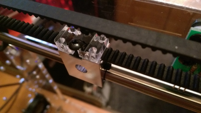 The screws and gears are adjusted to ensure that the slider and belt move smoothly. 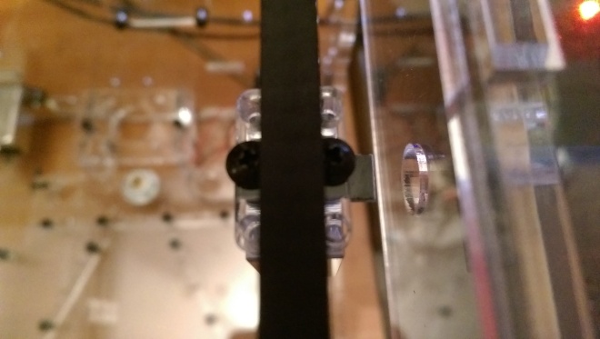 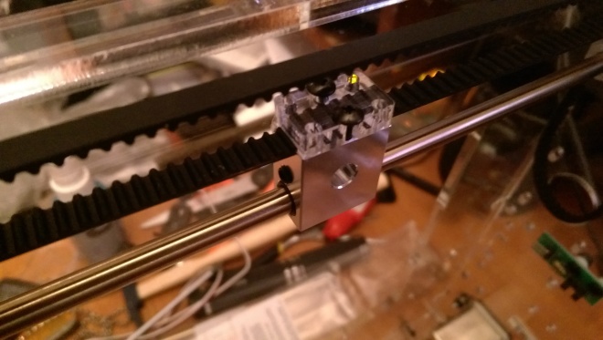 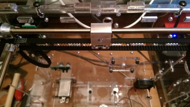 Finished 3D Printer, RB7, Hummer, Skyrider drone & Combat tank collection http://www.model-space.com/gb/
|
|
|
|
|
Great to see this one moving forward again Kenjara, looking good.... . Look forward to your next update.... Regards Alan
|
|
|
Rank: Super-Elite Groups: Registered, Forum Support Team, Administrators, Global Forum Support Team, Moderator, Official Builds Joined: 09/11/2012 Posts: 8,520 Points: 24,651 Location: East midlands
|
Hi Kenjara, Good to see you`re still on this one. Look`s like it`s all under control and look forward to the updates to follow. I`ve done pack three (not posted yet) and have 4-6 waiting in the wings, only due to other kits taking top spot in my available time. Will have to get a few bits done whilst waiting for things to dry/set on the other kits.  Keep up the good work.  Regards delboy271155 (Derek) COME BACK GUY FAWKES "YOUR COUNTRY NEEDS YOU"
|
|
|
Rank: Vice-Master Groups: Registered
Joined: 05/04/2013 Posts: 540 Points: 1,630 Location: England
|
Its been a while since I posted about my 3D printer build I ended blitzing through the second half in a short space of time. Here is a summary of the second half of the build. I maybe missing some photos as I switched phones half way through this lot. 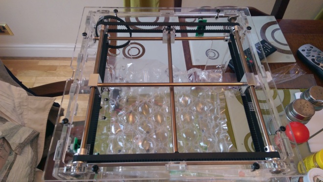 The sliders for the printer head are added. 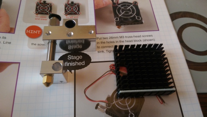 Here construction on the printer head begins. 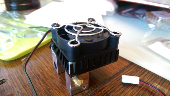 The cooling fan and heat sink is added.  The cartridge heater, thermistor is added. The cables are fed through a wire wrap to keep them tidy. 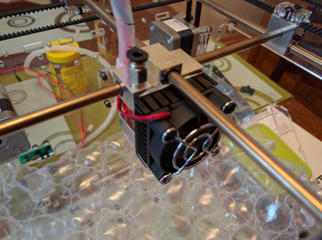 The printer head is added to the structure. The head moves around the x and y axis of the printer area and is responsible for heating and extruding the plastic. 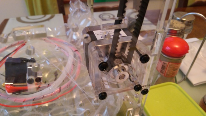 The x axis motor and timing pulley are added to the printer. 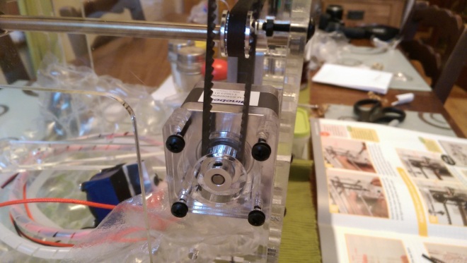 The Y axis motor and pulley are added to the printer.  The circuit board is added to the case. 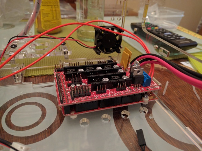 The driver board is attached to the lower circuit board. The cartridge heater (red cables) is plugged into the driver board (blue terminals). 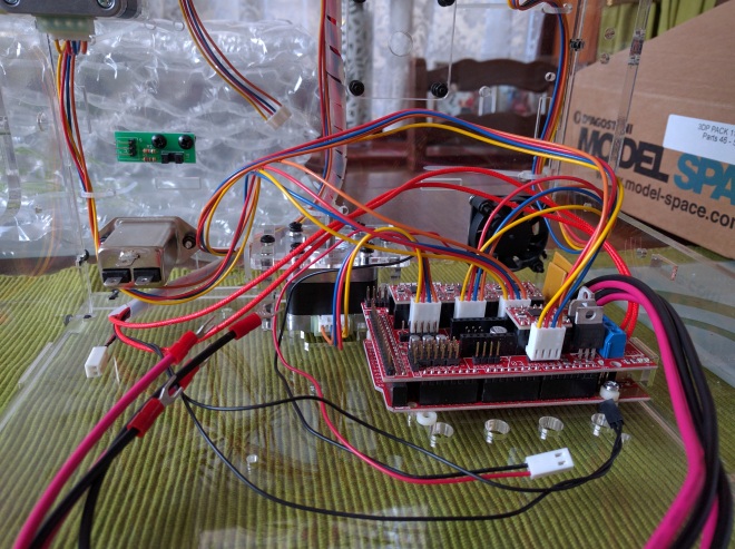 There is a motor driver board for each motor. These are added as each motor is plugged in. The Z axis motor is also added at this point. This motor controls the height of the printers table.  The power supply unit is prepared to be added to the printer. The input voltage is set to 230V for the UK.  Power and ground cables are attached to the terminals on the power supply. Next the thin black and read fan power cables are added. 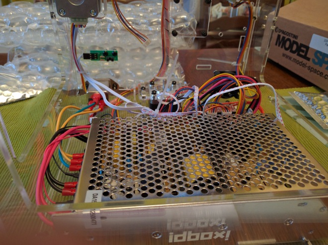 The cables from the driver board are added and the power supply is housed within the printer.  The table is added to the printer supported by the two Z axis rods. The table screw that enables the table to move up and down is attached to the z axis motor after being fed through the table.  The extruder arm is assembled and ready to be added to the printer. 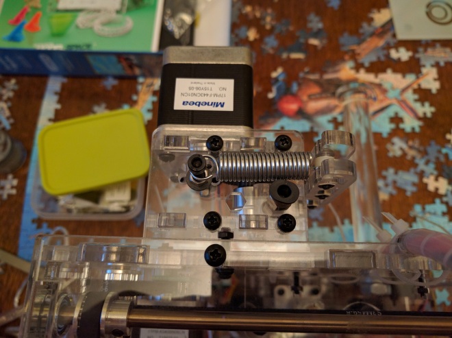 The arm is added to the extruder motor housing and is attached to the back of the printer. 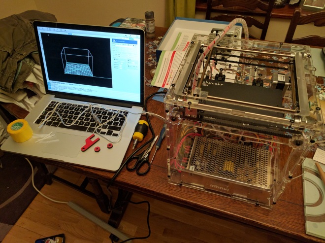 Two plastic surfaces are screwed in under the bed to cover the electronics. The printer is now ready to be configured. Finished 3D Printer, RB7, Hummer, Skyrider drone & Combat tank collection http://www.model-space.com/gb/
|
|
|
|
|
Coming along very nicely, looking great..... Looking forward to seeing some real masterpieces appearing...
Regards
Alan
|
|
|
|
Guest
|
 US
US

