|
|
 Rank: Pro    Groups: Registered
Joined: 23/03/2014 Posts: 185 Points: 545 Location: Essex
|
Again, thank you, Alan, for your kind comments. And we are in agreement regarding my fingers and the model.  I must admit yesterday's instalment described a bit more tension than there actually was. but I thought, why let the truth get in the way of a good story, eh?  . Anyway, today's build should be a bit more .... serene. Unfortunately when I started taking pictures this morning, I completely forgot to put the card in the camera which meant that I will have no evidence of it. But you should still be able to see part of the removal of the white overlap of the parts on this one. 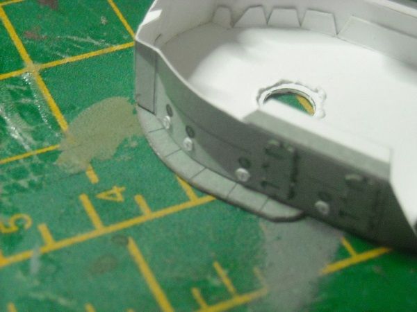 By that time I had already glued the platform on top of the wall and all that was needed there was a set of brackets. 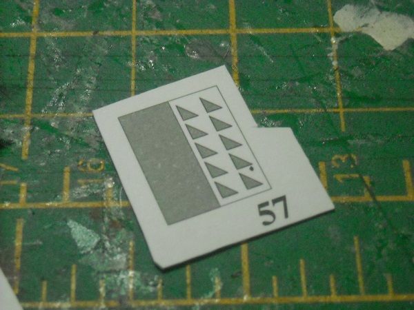 Small but straight lines so no real trouble. The two rectangles were glued back to back, left to dry and then cut out. A little edge painting on the side and they were ready to be installed. For this I used PVA glue. For one it dries quicker than the UHU but also dries up almost invisible. 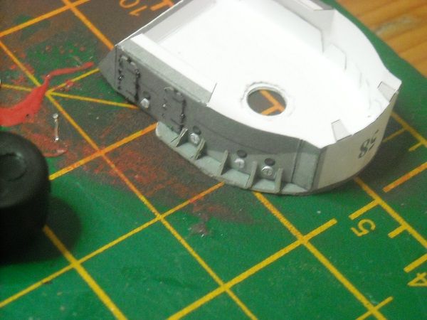 And the other side. 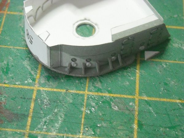 Whilst that was drying I went to the ship and painted the white front section of the superstructure. I did this to make sure that there were no ungainly white sections showing when the B-position was in place. Although there shouldn't have been, it is always best to be sure. 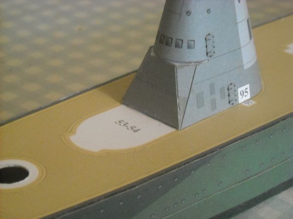 There was a bit of colour difference between the painted section and the part above it but when the position was in place, that difference was not noticeable.  Now all that was left for 'bathtub' B was the sidewall of it, which is part 58. 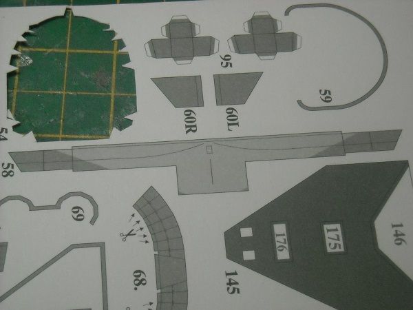 This caused me a bit more head-scratching. According to the instructions the top mm was supposed to be bent outwards and horizontal but the part was also to follow the shape of the previously installed platform. And according to me that rim would make it impossible to curve the wall as required. But since I have great faith in the designer of this model (JSC) I decided to give it a go as described. If you were wondering why the designer is JSC but this is a Scaldis model, the Dutch modelling club Scaldis worked together with JSC to release de Ruyter with this camouflage pattern. Since this version of the model can only be obtained through Scaldis (a standard grey version can be obtained from JSC) I used the name Scaldis in the model naming. But to get back to the build I cut the wall at the top, then turned over the card (which has a grey background, courtesy of JSC, and scored it from cut to cut. 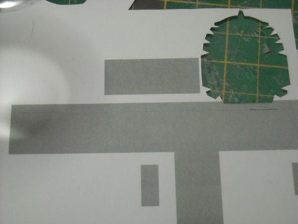 I then cut the remainder of the wall out and formed it with my fingers to get the round shape of the front of the former. In the back of the former there is a much smaller radial curve. To get this shape I used a small paintbrush to roll the wall around. When done, I was left with the following wall. 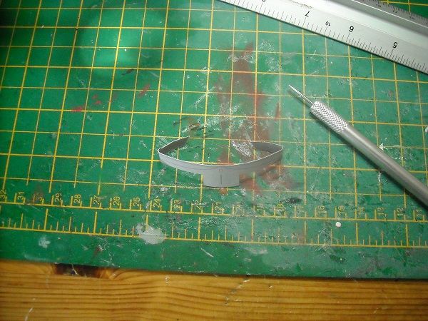 But then I bent the top mm outwards along the score line. 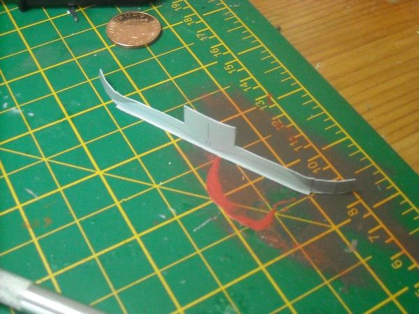 As I feared, the wall couldn't cope with both shapings. But there was only one way to go now and that is forwards, so I straightened the rim and glued the wall around the platform. I glued the curved parts first with the two backtabs bent inwards. 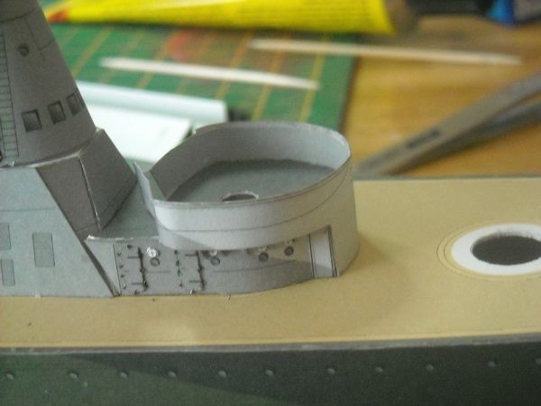 Once that was completely dry, I then pushed out the tabs to line up with the side of the former and the superstructure and glued them in place. 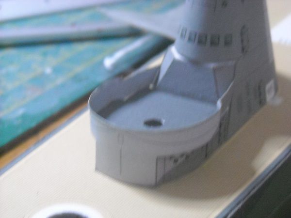 I left that to dry whilst we were going into town to do some shopping. One of the things I got was a new set of replacement blades. I had used nine so far and had only 4 left. The reason that I went through so many blades was that with a card model you only use the tip of it. And that one is easily damaged especially since there is a cutting mat underneath it. So I was looking for a different shape of blade, one with a much smaller cutting edge in the hope that that would make the blade sturdier. I found the following blades 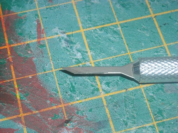 and am now testing it out. It feels completely different so not sure if I will keep using it. But time will tell. Anyway, when we got back, I decided to give the second bend another go and just using fingers the rim came down without a problem! Now that I did not expect! A railing is to go on top the rim and that was quickly cut out. 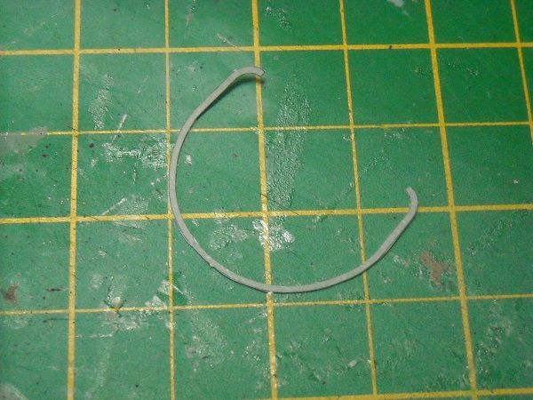 Edge painting it on the in- and outside of the rim and I glued it in place with UHU, because of the longer curing time so I had time to move the railing around when needed. But it went down easily after which I used a tweezer to make sure that the railing was glued well against the rim. 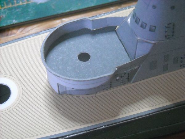 All that was left to do was two distance pieces/walls that needed to be scored, bent and glued to the platform. 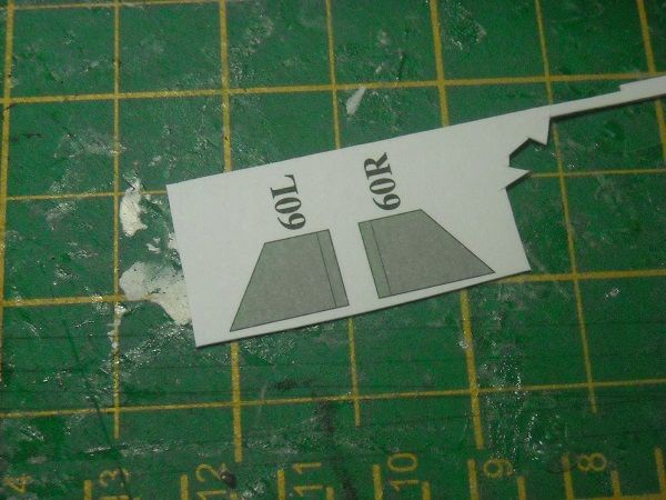 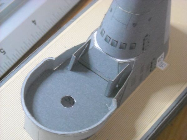 Once everything has dried thoroughly I will use some PVA glue with a toothpick to fill in any open gaps like the one that can be seen in the last photograph. But for the B-position, that is now complete. The following section will be the next platform. I have now used parts up to No 60. Since there are 299 numbered parts in total, I guess I will be here a while longer.  So, until the next time, then!!! Adrie. 'Where to glue or where not to glue, that is the question'
Building: Hr. Ms. de Ruyter (card), Retourschip Batavia (Revell), HMS Surprise (De Agostini)
Built (and sunk): Too many to list
|
|
|
 Rank: Super-Elite      Groups: Registered
Joined: 30/01/2013 Posts: 4,604 Points: 13,607 Location: Monmouthshire UK
|
Very nice Adrie, never used to think that card models had this much detail, really good work Steve
|
|
|
|
|
Only 239 parts to go Adrie so can believe you will be with us for a while and guess what.... I'll be with you all the way.... .. Well done.... Regards Alan
|
|
|
Rank: Pro Groups: Registered
Joined: 23/03/2014 Posts: 185 Points: 545 Location: Essex
|
Hi guys, thanks for staying with me.  It's much appreciated. It is, of course, the benefit of the large scale that allows great detail. That, and the designer, of course. . That and the 10 A4 sheets of parts, of course. But on a more serious note, the 299 parts that I mentioned are the numbered parts. Of some of them there are eight or ten in total with that number. Then adding the metal rod-pieces that are going to be needed and the extra detail parts (like those BLEEPing doors!) I reckon there are going to be 500 to 600 parts in total! So I will have plenty of time while my Surprise installments are arriving. But we'll take the build one step at a time and as luck would have it .... here's the next one! We are working our way upwards along the forward superstructure. So after 'bathtub B' we are going to work on the platform above it. Like the previous platform, this consists of two layers that need to be glued back to back. Then once dry, the white rims were cut away like before. 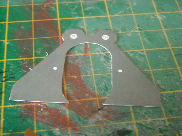 There's still a bit of cutting required there and once that was done, the platform was inserted in position on the superstructure. 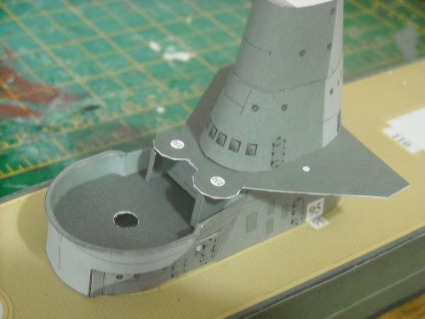 This side looks ok. 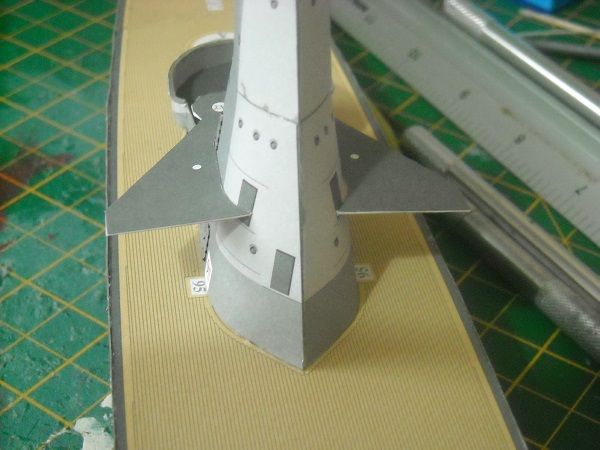 This side needs a little bit of work to fit snugly around the column. You do this by cutting away slithers of card in the area where there is too much, then place it back, check the fit, take it out, cut it some more, etcetera, etcetera. I did it like this to make sure that I didn't cut away too much. When I was happy with the fit, I decided not to glue the platfom in place yet but to add the sidewalls first. These walls give the platform card a lot of stiffness so makes it easier to handle and position it. The walls were made up from a wall and a railing part. As before, the top of the wall was to be bent outwards for the railing to lie on. Them bits ... 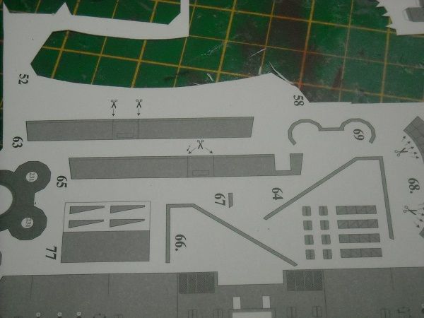 ... cut out ... 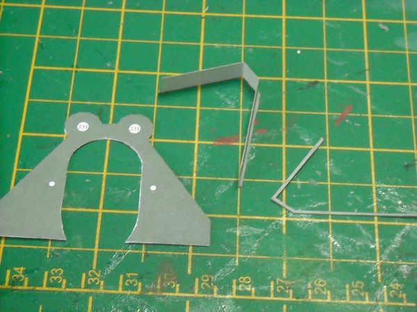 and glued together after scoring and bending the top of the wall. 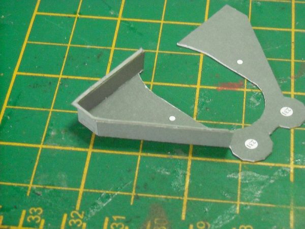 I did the same for the other side. It took me a while to get it all lined up nicely because the angles on the railing were all in the wrong place but finally they lay nicely and tried the platform on the superstructure. It turned out that not only were the angled sides wrong, but that the aft lengths of the wall were too long. I had to cut them to fit.  But that was a temporary state of mind because soon after I could finally glue the platform down. 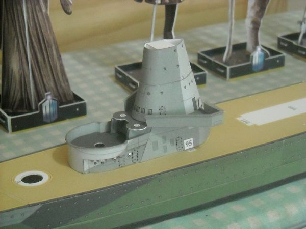 Which only left the forward wall section to do, which was oddly shaped. 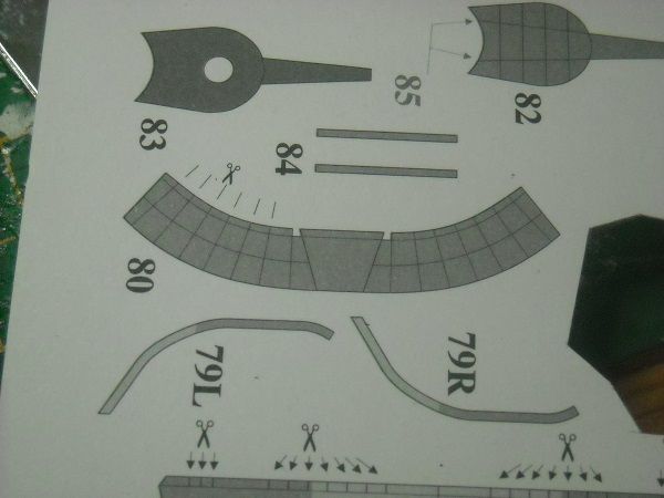 The end look should become clear from this next part which was the railing for it. 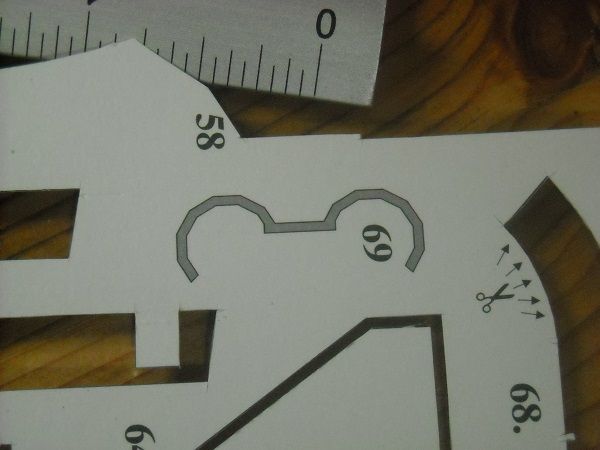 After quite a bit of scoring, bending and cutting I got the general shape right, or so I thought. 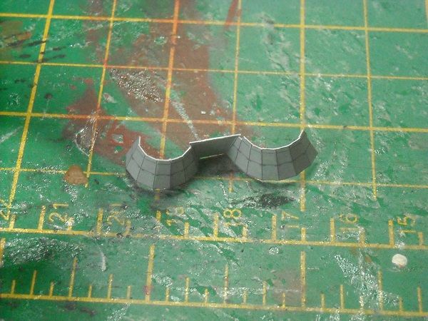 Unfortunately the part didn't agree when I married it up with the edge of the platform. The centre and the bent sections were oversize with a gap of about 0.5 mm. This doesn't sound much but on this model it stands out like a sore thumb. I decided to cut out the centre bottom part which gave a bit more room to fit the wall around the platform and 'spread' the gap around. 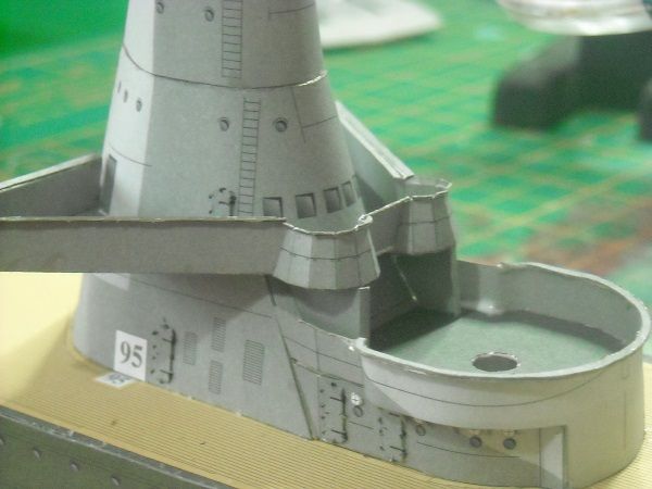 I'll have to touch up the bottom of the central section but overall I thought I got away with it! That was until I placed the railing on top of the wall. 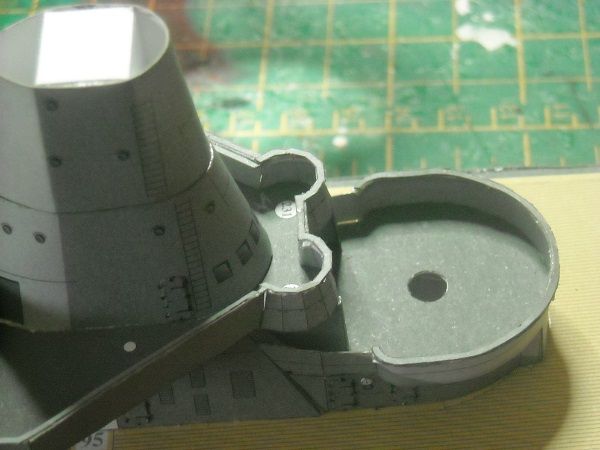 You can clearly see where the railing does not cover the wall. That will need some additional cutting and painting, but I'm pretty sure that not much will be visible afterwards. On the whole I am a bit peefed about this after having had a good fit so far but it's not the end of the world. It still looks good and will look better after I pretend to be a surgeon for an hour. Oh, and I should also start on the creation of the railings. The model has a acetate sheet with the railings printed on them so you could cut them out and put them on the model but I think I can do better. 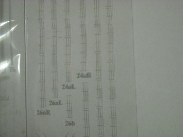 All I am going to need is cling film, black thread, water, PVA glue and plenty of time. Hmmm, what else could I do with that, I wonder?? Anyway, until the next time!!! Adrie. 'Where to glue or where not to glue, that is the question'
Building: Hr. Ms. de Ruyter (card), Retourschip Batavia (Revell), HMS Surprise (De Agostini)
Built (and sunk): Too many to list
|
|
|
|
|
Just gets better and better Adrie, will be looking forward to see what you do with cling film, PVA and thread..... better you than me.... Regards Alan
|
|
|
|
|
I'm with Alan, Adrie, brilliant work and very well described with all the pitfalls to look out for! A really interesting diary!  Judging by the legs, I'd say the Guard detail is increasing as well! Keep them coming! Robin First wooden ship: The Grimsby 12 Gun 'Frigate' by Constructo Second: Bounty DelPrado Part Works Third: HMS Victory DelPrado Part Works 1/100 scale Diorama of the Battle of the Brandywine from the American Revolutionary War Diorama of the Battle of New Falkland (unfinished sci-fi), Great War Centenary Diorama of the Messines Ridge Assault Index for the Victory diary is on page 1
|
|
|
 Rank: Master  Groups: Registered
Joined: 08/07/2010 Posts: 1,036 Points: 3,086 Location: Thetford, Norfolk, UK
|
Hi Adrie What a grand job you're making off this, and the diary is a joy to follow. I'm afraid you've piqued my curiosity on this branch of the hobby and I found myself following the link you gave to the free 'San Salvador' model which I downloaded and printed out, but unfortunately made a real mess of it - I used some old A4 'craft card' that I had which I thought would be thick enough for the job but alas, no such luck and it ended being far to floppy. Still interested in trying something though, so I ordered the book on cardboard modelling from Marcle models. Thought you might like the link if you haven't already seen it www.marcle.co.uk So I'm going to have a good read up before I go any further but you've definitely whetted my appetite now Thanks and happy building David
|
|
|
Rank: Pro Groups: Registered
Joined: 23/03/2014 Posts: 185 Points: 545 Location: Essex
|
Guys, what can I say. Apart from thank you for your kind comments. I will endeavour to keep doing them justice. Oh, and Robin? Sorry, I completely forgot to introduce you to the gang. Apparently these guards are on a 1/5 rota which was agreed with their union or something. So they guard the ship for an hour then have 5 hours off. As luck would have it, that means that 6 guards are required to keep up the surveillance. Hence: 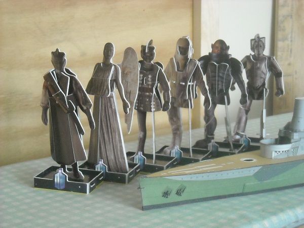 Note: this picture was taken when they had a union meeting for which they claim a 30 minute break. Not sure why they would need a meeting every hour, though! Adrie 'Where to glue or where not to glue, that is the question'
Building: Hr. Ms. de Ruyter (card), Retourschip Batavia (Revell), HMS Surprise (De Agostini)
Built (and sunk): Too many to list
|
|
|
Rank: Pro Groups: Registered
Joined: 23/03/2014 Posts: 185 Points: 545 Location: Essex
|
Hi David, I am glad I managed to drag you to 'the Dark Side'. There can be quite a bit of confusion about what is the right card to use, etcetera, and sometimes I make up my own mind. As with the decks in this build. I am glad that I took the effort to give it a bit of extra strength, which made the lining up of the sides as well as the placing of the superstructure so much easier. I guess that boils down to a bit of experience but as far as I am concerned every model should have at least one central section that is sturdy. The card-thicknesses I use are as follows: printer paper (90 g/m2) light card (220 g/m2) heavy card (400, 750 and 1500 g/m2) The heavy card tends to be named for the thickness, rather than the weight, so they are 0.5 mm, 1.0 mm and 2.0 mm thick, respectively. These cards can be reasonably easily obtained. I believe the website you linked to sells it as well. And I did visit them before.  The light card I picked up at Works, with 20 sheets for a pound, or thereabouts. But you have to buy the cards to fit the size of the part-sheets. So if you get a model that uses A4 (or letter) size sheets, you should use an A4 size card to laminate on, a bigger scale model like a 1:200 battleship tends to be supplied in A3 so you'll need A3 size cards to laminate it to. Laminating (thickening) itself is relatively easy. All you need is the sheet with parts, the thick cardboard and a can of display mount. I use the permanent mount from 3M. Just spray it on the card, let it dry for a minute and place the part-sheet on top of the card. However, you must then put pressure on it duting curing (which takes about 1 day) to stop the card from warping. Normally a couple of heavy books is sufficent (plus a flat background, of course [grin]). I saw the thickness-instructions for the galleon but I fear I disagree with them there. I don't know of any supplier that will supply card of 0.75 - 0.8 mm, nor 1.75 - 1.80 mm. It tends to be 0.5, 1.0, 1.5 or 2.0 mm. If I know that a section needs the be laminated onto thick card, then I don't print it out on light card but on printer paper and laminate that. So for me I would print out the sheet onto printer paper (with the highest resolution) then roughly cut out the parts that need to be laminated onto 2 mm and laminate those on the 2 mm cardboard, and then roughly cut out the bits that need to be laminated to 1 mm and do the same. The rest (if there is anything left) will then be glued to the light card. The parts that don't need laminating are printed on light card. With a (rough) thinkness for printer paper of 80 microns (1/1000 mm), the end-result of laminating that to 2 mm card would be in the area of 2.09 mm (an extra 10 microns for the laminating glue), and that should be close enough to the required 2.0 mm. The nice thing about the 220 g/m2 card (which is also used on the commercially available model books) is that while it is relatively stiff it is at the same time easy to bend and shape. But I agree, on it's own it is not 'tough' enough for a sturdy base. I hope this helps and hope you'll get plenty of pointers from that book! Of course, if you have any questions or queries, then please do not hesitate to give me the opportunity to 'muddy the waters'. Adrie 'Where to glue or where not to glue, that is the question'
Building: Hr. Ms. de Ruyter (card), Retourschip Batavia (Revell), HMS Surprise (De Agostini)
Built (and sunk): Too many to list
|
|
|
Rank: Master Groups: Registered
Joined: 08/07/2010 Posts: 1,036 Points: 3,086 Location: Thetford, Norfolk, UK
|
Thanks Adrie
That's a lot of very useful information on card types and use of lamination, thank you.
The book turned up in today's post so I'm going to have a good read of that before I try another model (actually, there was a very simple model included with the book). Then I'll get online and order some card to get me started, unfortunately, we don't have a branch of The Works in my area (where I used to live there was an enormous branch which being the bookworm that I am, I was in there practically every week). Just thought as I'm writing that they may have a website and yes they have!
So once again thanks for the info and I'll keep tuning in to your diary.
Happy building
David
|
|
|
Rank: Pro Groups: Registered
Joined: 23/03/2014 Posts: 185 Points: 545 Location: Essex
|
You're welcome, David. The main thing is to take your time but most importantly, to have fun! Talking about having fun .... Tada! The next installment!!! When I rechecked the problem area again yesterday it suddenly struck me that: -A the parts that I wanted to cut away were in fact the walls so any removal would create gaping holes!  and -B the problem areas are going to sport two double machinegun posts. With any luck they will capture the view so nobody would ever notice the issues. So, onwards we go! Oh yeah, the riddle of the ingredients. Here's one. 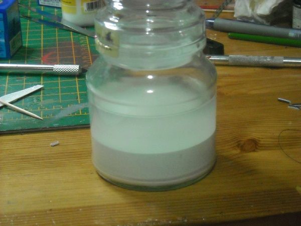 One jar with a mixture of half and half water and PVA glue. If you leave it to stand for a while it will segregate out but a quick stir afterwards will combine them together again. And here's two. 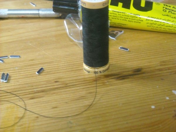 Bog standard black sewing thread. Now I know there are quite a few PE emhancement sets out there that you can turn to if you require a bit more detail but personally I don't think that this model needs it. Also it is 1/250 for which scale there aren't that many PE sets out there. But we'll have to construct the the railings from something and that something is stiffened thread. It's a quite common material to use in situations like this. For one it is in plentiful supply and furthermore easy to glue with PVA. To stiffen the thread, all you have to do is to cut off a length (I took about 2 metres), keep one end with a pair of tweezers and with a swirling motion deposit the thread into the jar, still keeping hold of the one end. If you drop it, you'll be cursing for a long time! Let the thread soak up the mixture for about 15 seconds then slowly pull it back up, at the same time rolling it between index finger and thumb, to remove the outside water/glue mixture as well as straightening the thread fibres. Once you get the whole of the thread out, attach two pegs to the ends and hang it to dry for a night. Oh, and it would be beneficial to keep a piece of newspaper underneath the thread while it is drying. The pegs (NON PINK!!!!! ) are to keep the threads apart and keep them taut.  I know it's hard to see the thread but you'll get the general idea. I will be making a thread like that for 5 nights and that should give me enough thread to do several railings. Oh, and I am dropping the requirement for cling film. I wanted to used it as a cover over the acetate sheet to make it easier for the glued together thread to be removed from the acetate but when I asked the mizzus for the film and explained what it was for, she immediately said that it would never work. Why not, I hear you ask?  This is the ultimate idea, to use pins that are pushed into the cardboard with the acetate above it to pin down the acetate but more importantly to act as guides for the threads. The pins are at an angle to force the thread to stay on the acetate. Once all the horizontal and vertical threads are in place a bit of brushing with more of the water PVA mixture and hey presto, a relatively stiff piece of railing, ready to be painted and put in place. It's going to take a bit of time but I should be able to do it on the side while continuing with the build. And the pins were the problem, that my mizzus immediately spotted. They make holes in the cling film and acetate so any watery glue will just seep through as well as tear the cling film when keeping it taut over the acetate. So scratch that one! Well, that's the theory in a nutshell, anyway. I'll keep you posted on how things are going. Which brings us back to the build. The next level up from the command platform are two lookout stations (well, I assume that's what they are) which are placed just above the mentioned platform on either side of the structure. 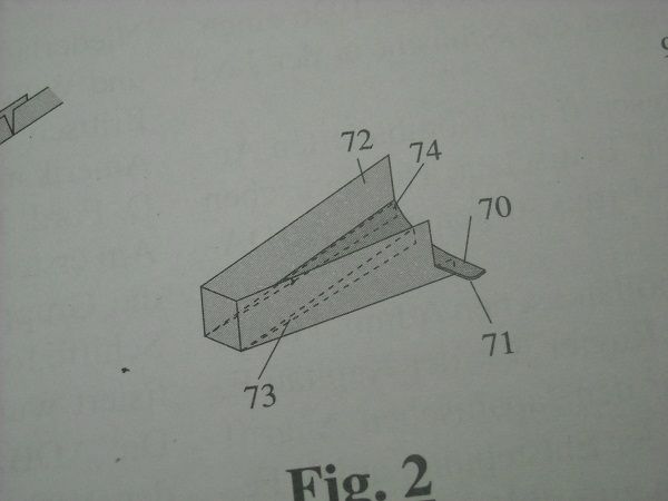 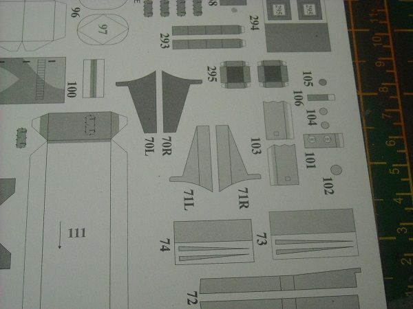 The required parts are 70 through to 74. There was a bit of a confusing moment when I deduced from the drawing that the platform would need to be bent but upon closer examination that was not the case. The curve at the back of the platform appeared as a downwards bend. But cutting out the wall and checking it for height, it showed that the platform itself was supposed to be straight. (The bottom of the platform is to be on the same level as the bottom of the opposite side and fit on top of the lip in the foreground.) 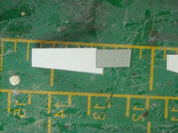 So it was all good and after glueing the platform parts, cutting away the white sides and glueing it to the wall, the end result was good. 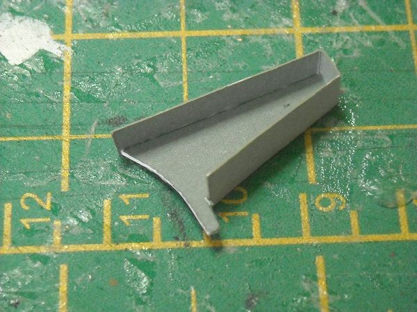 Then the triangular supports were glued together, cut out and glued to the bottom. 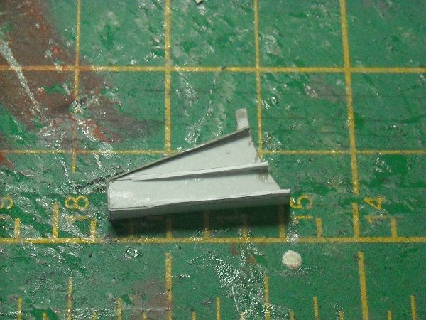 After drying the part was then glued to the side of the structure, 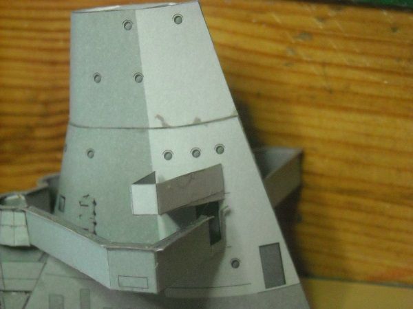 I wasn't too happy about the angle of it as it was attached so I used a distance piece (what I would do without toothpicks, I have no idea!!!) and let the glue dry thoroughly. 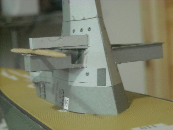 I'll finish fitting the second outlook position when the glue has set so that tomorrow I can tackle the next section, namely the top of the structure with the following bits. 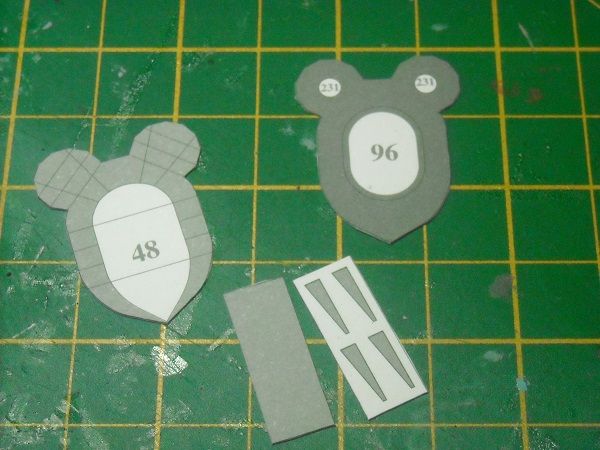 But more about that tomorrow! Now I have an urgent meeting with a a pair of tweezers, a piece of thread and a jar with a strange liquid!!!!! Until the next time! Adrie. 'Where to glue or where not to glue, that is the question'
Building: Hr. Ms. de Ruyter (card), Retourschip Batavia (Revell), HMS Surprise (De Agostini)
Built (and sunk): Too many to list
|
|
|
Rank: Pro Groups: Registered
Joined: 23/03/2014 Posts: 185 Points: 545 Location: Essex
|
Hi all, I had a productive day today so I decided to have an early diary entry and then have the evening off. I'm sure me and the mizzus can find something else to do. But enough about that , let's get cracking! As I was starting work on the top of the conning tower (penultimate picture from yesterday, I suddenly realised it had a dodecagon shape, just like the one I had the trouble with before! I wondered if I would face the same issues here. 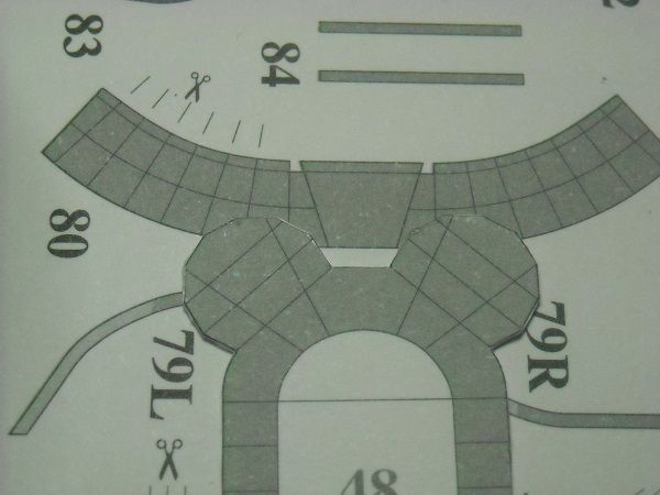 And yes, the central section was again too wide. But at least this time I was forewarned! With a pencil I made marks where I would have to cut to make the centre section fit. 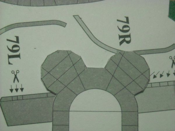 After doing the required cuts I checked the platform against the wall and found it to be ok. 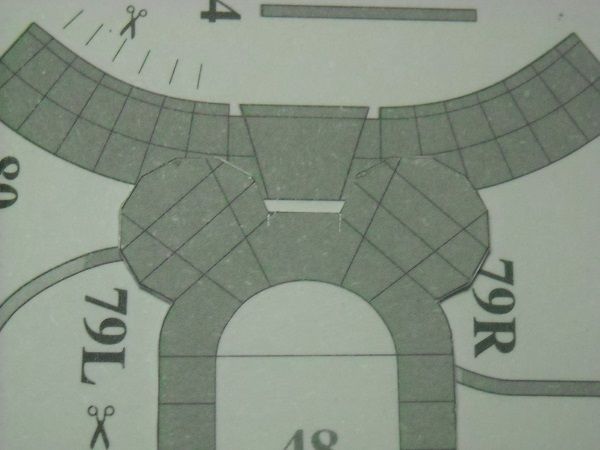 I cut out the wall to check the size of the sections which needed to be scored and found them to be ok as well. So all systems go! But NO! 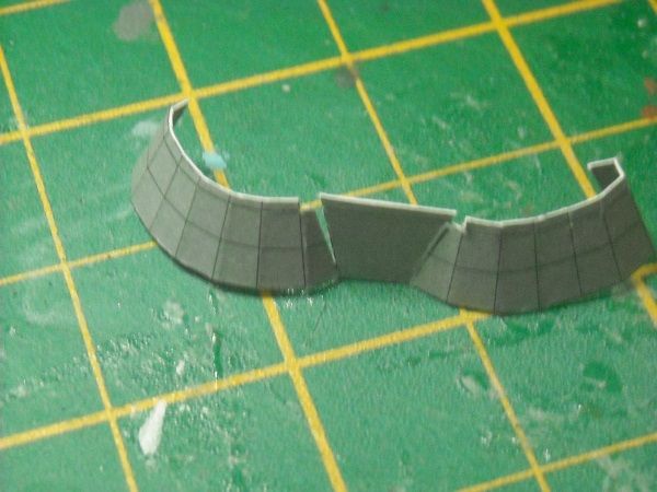 After scoring the above wall, the section next to the centre tore on the score line! Luckily that wasn't too big of an issue. All that was needed was a piece of printer paper glued behind the wall ..... 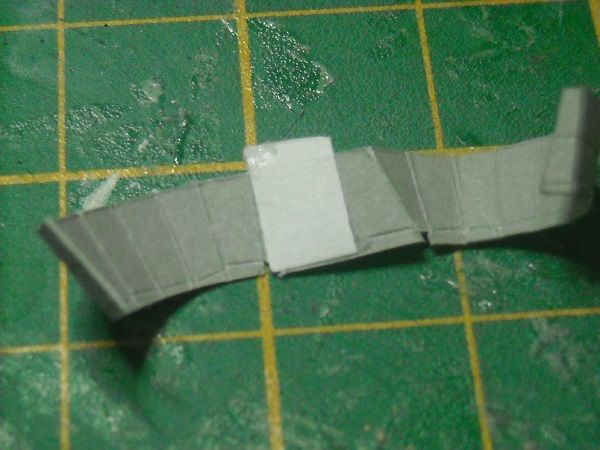 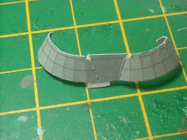 ... cutting it to size and painting it in a relatively similar colour. 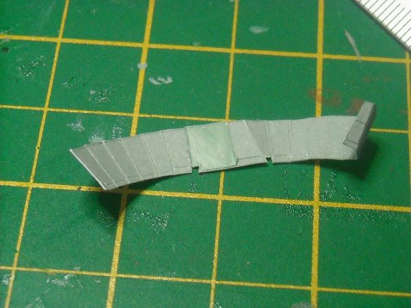 The reason to glue the bit BEHIND the wall is so that the colour doesn't have to be too close because the back will not be that visible. Having rescued the wall, it was then dry-fitted, checked and then glued in place. 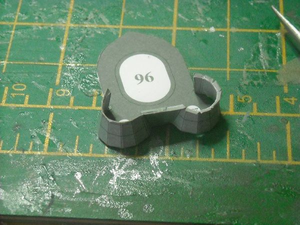 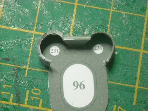 A much better fit! There is a little gap in the front of it but a little drip of glue will soon fix that! The covering railing was then placed over it. I'm not too happy with the fit of these parts but it's good enough, considering that there will be another pair of double machinegun turrets in front of them. 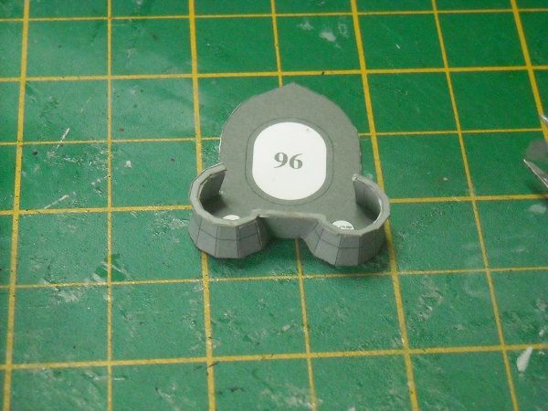 Then the aft section of the wall was cut out, rolled with the fingers, scored, bent and glued in place. Again the railing showed poor fit but I was happy with the overall looks. 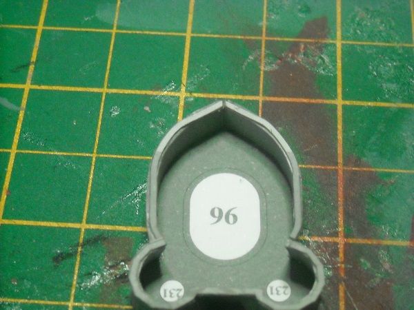 Four supports where then cut out and glued to the bottom ... 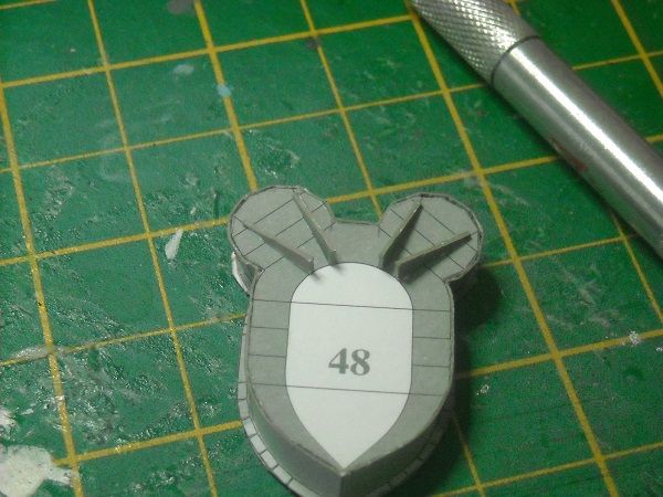 ... and once dry the top was then glued to the top of the conning tower. 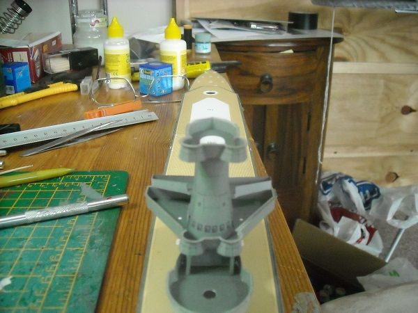 Job done! The next section was the central searchlight platform.  Compared with the previous sections this was quite straight forward. The two platform pieces were glued together as were the two support pieces. All parts were then cut out, the support glued at the bottom and the 'walls' were glued to the side of the platform.  This was then glued to the indicated position at the front of the conning tower. 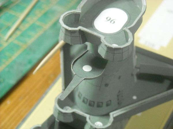 Another job done!! 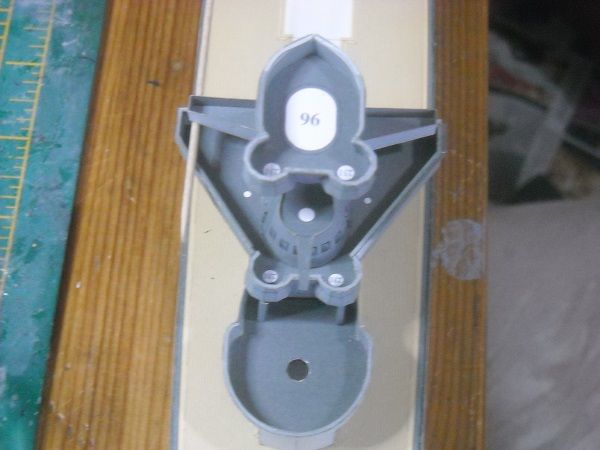 Just below the searchlight platform another lookout station is required. Them bits ... 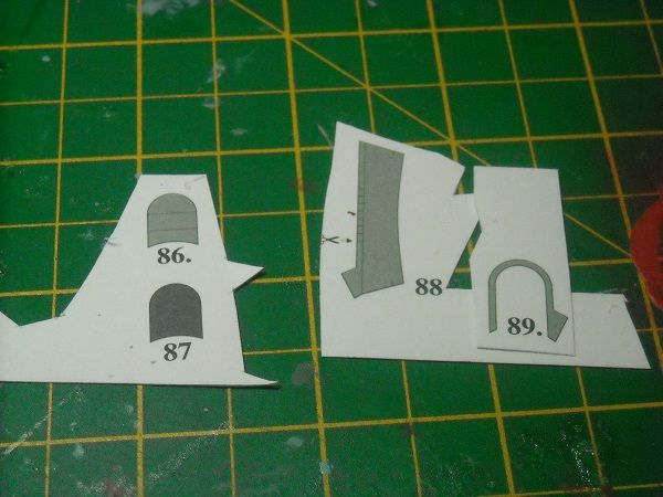 ... and glued together. 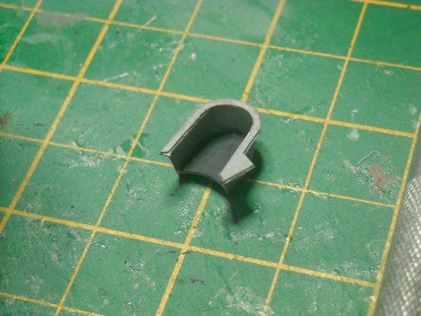 Again the railing was of poor fit. Do I see a pattern developing here or is this a sign I'm not that good with them? Could be either, really. But I'm happy with the overall look, so I glued it to conning tower. 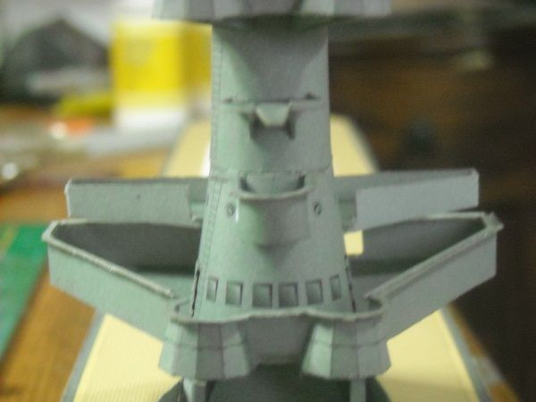 Which I then removed again because it was stuck to the tower at an angle. I repositioned it. 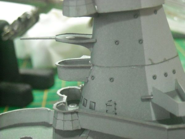 And that's where I got to today. I have something else still to share with you, though. 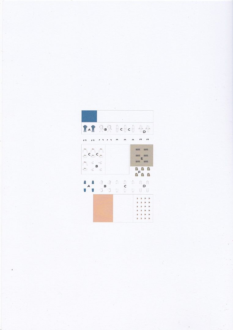 I found a pdf file on the web made by David Hathaway (of Paper Shipwright fame), showing a number of 1/250 size sailors. They are to be made of cardboard (of course!!!!) They will be tiny (about 7 mm high) !!!! I said before that this model was good enough not to need extra bits to look good but I am pondering whether I should use these. The uniforms (apart from the Captain's one) are similar to the ones from Dutch sailors in south east Asia wore and I could use them to good effect but then again, how silly would it look if I placed just a handful on such a big ship. And to get four or five sets of mariners all shaped the same is going to look ridiculous. So I'm not sure whether I should or not. What do you think??? Adrie. 'Where to glue or where not to glue, that is the question'
Building: Hr. Ms. de Ruyter (card), Retourschip Batavia (Revell), HMS Surprise (De Agostini)
Built (and sunk): Too many to list
|
|
|
Rank: Pro Groups: Registered
Joined: 23/03/2014 Posts: 185 Points: 545 Location: Essex
|
Hi all. I fear I must apologise to you all. No really. I must. If the mizzes says I must then ......  Anyway, she was a bit miffed with my last diary entry and humphed: "How are they supposed to be able to give you advice when they can't even see the figures?" Okay, she does have a point there so I have taken the camera and made some snapshots. At the same time I will construct one of these 'guys' and see what the overall effect is. So here are the bits. 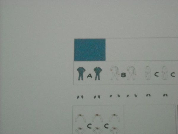 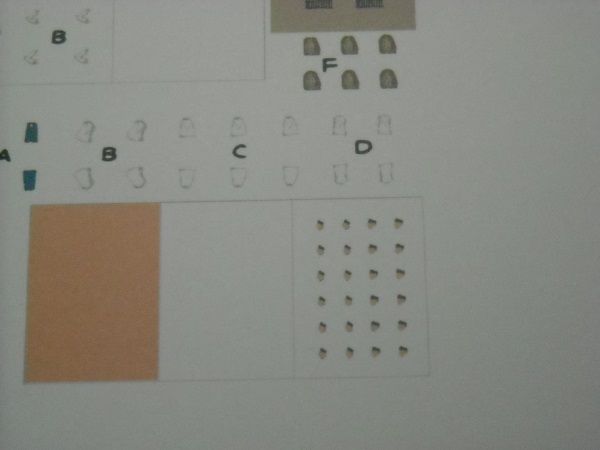 Why there are so many heads when there are only 8 bodies, I have no idea. Well, after trying one I now know why .... They are smaller than a dust-particle so there is every chance that one (or more) will get lost along the way. I decided to have a go at the Captain's figurine, if for no other reason that I couldn't use it even if I wanted to, because Dutch Captains of that period wore white uniforms just like the sailors. The Captain's bits ... 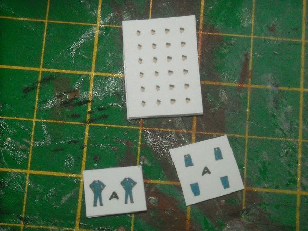 ... the main body cut out ... 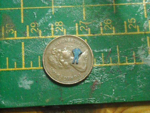 ... and the body front added ... 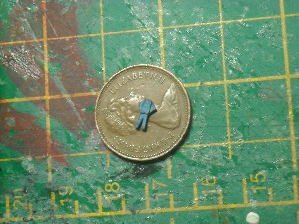 ... as well as the back part ... 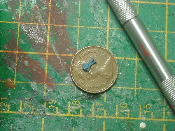 ... and finally the head. (DON'T cough!!!)  With a bit of edge-painting and glued to his shoes ... 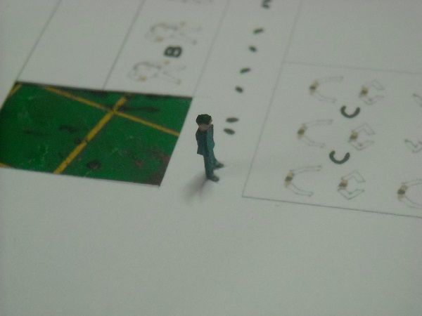 ... and in a possible final position on the ship 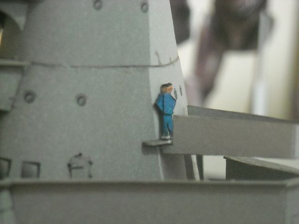 Is it noticeable from 'far' away? 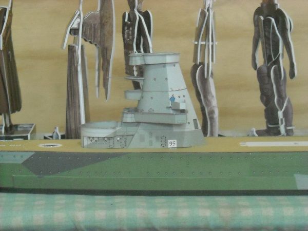 They are more 3D then I originally thought, but with an build time of 45 min each and only 3 poses to chose from .... I am still undecided, so PLEASE help me out here. Should I or shouldn't I? Adrie. 'Where to glue or where not to glue, that is the question'
Building: Hr. Ms. de Ruyter (card), Retourschip Batavia (Revell), HMS Surprise (De Agostini)
Built (and sunk): Too many to list
|
|
|
|
|
Hi Adrie just picked up on this one stunning build but I think the men look like ones out of minecraft Still Love the ship bril work Rgd Martyn Building ?
Completed. Soliei Royal . Sovereign of the Seas . Virginia . Scotland . San Felipe . Corel vasa , Santisima Trinadad X section , Vasa
Next Build ?
When sailors have good wine, They think themselves in heaven for the time. John Baltharpe
|
|
|
Rank: Super-Elite Groups: Registered
Joined: 30/01/2013 Posts: 4,604 Points: 13,607 Location: Monmouthshire UK
|
Absolutely fantastic skill there Adrie, really nice build....The sailors are also a work of art in miniature form and you are right they do have a nice 3d effect and it is down to personal opinion if you use them. You say the model dosent need them and I think agree, the ship is fab without them and I dont think I would use them, however I admire you if you go ahead and make a hundred of the little chaps though BTW, do you think the crew are just very slightly larger scale than the ship? Not sure how big they should be compared to the hatches though so id have to see a photo Steve
|
|
|
Rank: Master Groups: Registered
Joined: 08/07/2010 Posts: 1,036 Points: 3,086 Location: Thetford, Norfolk, UK
|
Hi Adrie, Well, in my humble opinion the figures will detract from what is a fine build, and how many times have we seen figures on the decks of museum models? Why don't you set up a poll so members can take a vote on the subject? Carry on with that super build and forget the figures Happy building David PS: The book I ordered is very informative and I've just found another free model on the web which I've downloaded and printed out ready to use your lamination technique for the framework. I might be trying to 'run before I can walk' here though as there are lots of very very small parts to prick out, again using your technique. The model is of a WW2 Class VII-c German u-boat. if you're interested here's the link: http://udonfactory.the-ninja.jp/paper/lev/U-VIIC.htmlThe instructions are all in Japanese but there's a photo to illustrate each build stage.
|
|
|
Rank: Pro Groups: Registered
Joined: 23/03/2014 Posts: 185 Points: 545 Location: Essex
|
@Martyn A belated welcome, Martyn. What kept you? Many thanks for the kind words and I must completely agree with you. They are very Minecraft-ish. Now don't be a stranger, you hear? @Steve You know, that is a really scary thought, 100 of these little blighters. . I tend to agree with you, though, so I am hoping nobody can come up with the ultimate reason why I would HAVE to do it . As with regards to the overall size, I think they are almost spot on. 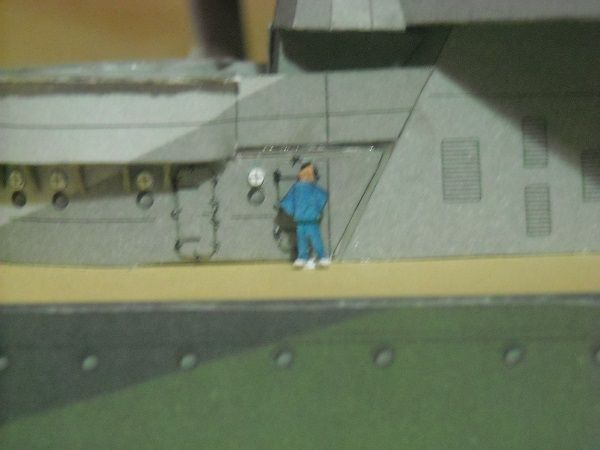 The top of his .... 'head' is just below the top rim of the door so he would have to bend to walk through it, which I think was the common practice. Do you agree? @David That is one mean looking model there! Looks extremely detailed so should be an interesting model. Just remember, if something goes wrong, you can always re-print the sheet and start again! . However, seeing the photo's taken, personally I would see if I knew a Japanese who could help me with a translation. Mind you, the only Japanese that I know is on this forum so you might not have one in your contacts list either. But the number of sheets to download suggest me that it is going to be very detailed so an excellent find! And I acted on your suggestion but if you saw my response to Steve, you might imagine which option I hope gets the most votes. . But enough of that now, it's time to get cracking again. I must admit I didn't get that much done today, my mizzes wanted me to make a pot of nasi again and I do love that meal. But today I managed to finish the last searchlight platforms on the conning tower, one on each side. The last section will be an observation post at the top of the conning tower. But first the searchlight platforms! 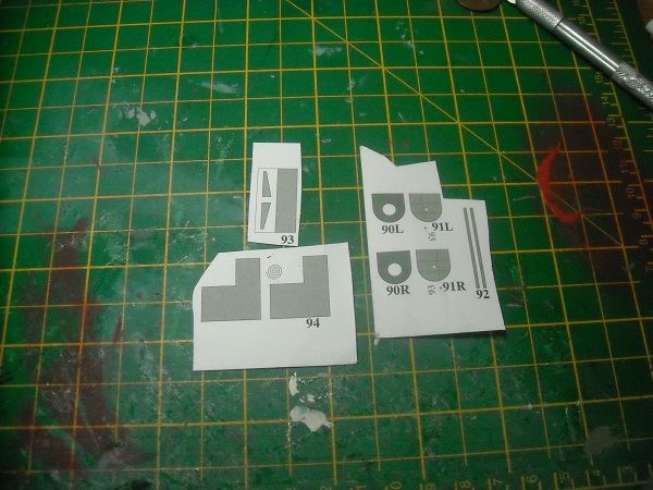 Just like with the forward platform there will be the platform itself (the searchligths will be placed at the end of the build), a rim and a support but there is also going to be a stepped support column. This column will have to be tightly rolled, something that will be required in a lot of cardboard model building. And a lot of cardbuikders hate this with a passion and rather use plastic or metal rods instead. But like everything all it requires is attention and sufficient time. To roll a part tightly, you must first re-align it's fibres. But because of the tightness of the roll you have to make sure all of the fibres get the message. So you preform the part but you need something stronger than your fingers. I use three different sizes of brushes (big, smaller then small) and to top it of I use a toothpick. 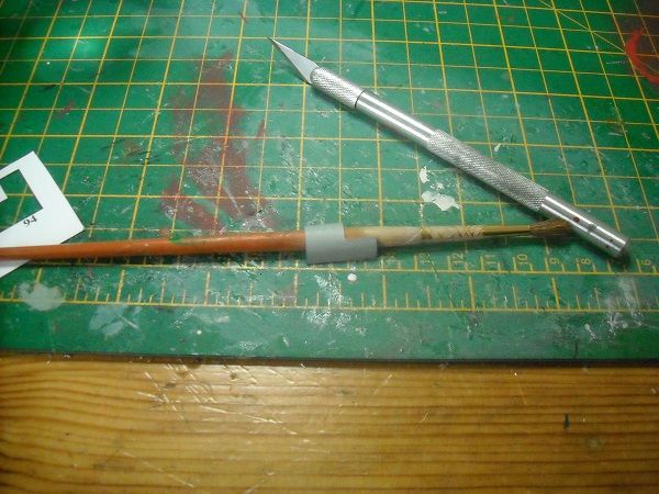 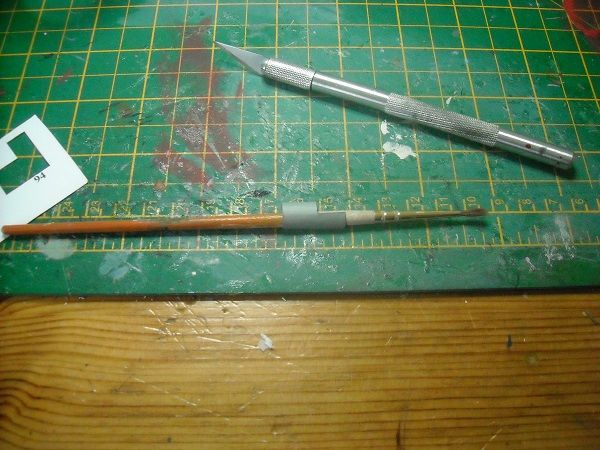 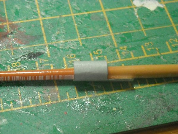 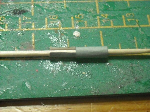 With all these you have to make sure that all of the part is curved and once they have gone through these four steps, I then take the rolled up part and roll it between my index finger and thumb putting more pressure on the part as the finger rolling continues. Once I am happy that it is as tight as possible I open the part up again and put a layer of UHU glue on the back of the part after which I roll the part again between my fingers until the glue sets. I use UHU here because a PVA glue would harden too quickly and there is a good chance there will still be a hole in the centre of the rolled part. 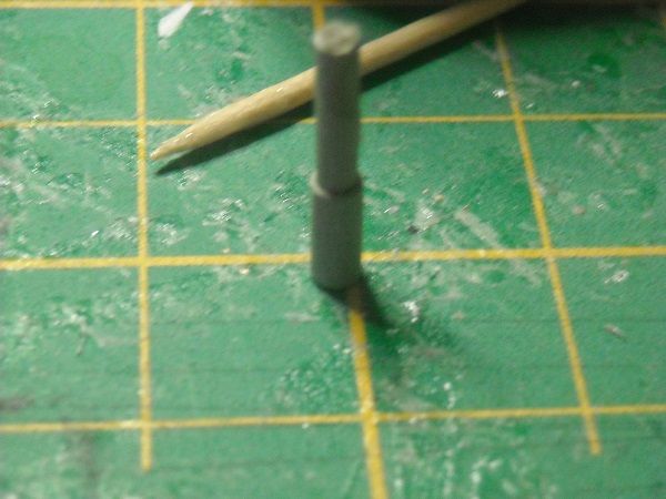 The photo isn't too great but the shape is!!! This shaping is difficult but can be done if you take sufficient time. But as always doing it several times is the best way to learn it. I decided to make the columns first because they will connect the platforms to the main platform we installed a couple of nioghts before.(the one with the wonky dodecanol fronts) But once the colums were made, the platforms were cut out, glued back to back, the rim was installed around it and the support glued underneath. 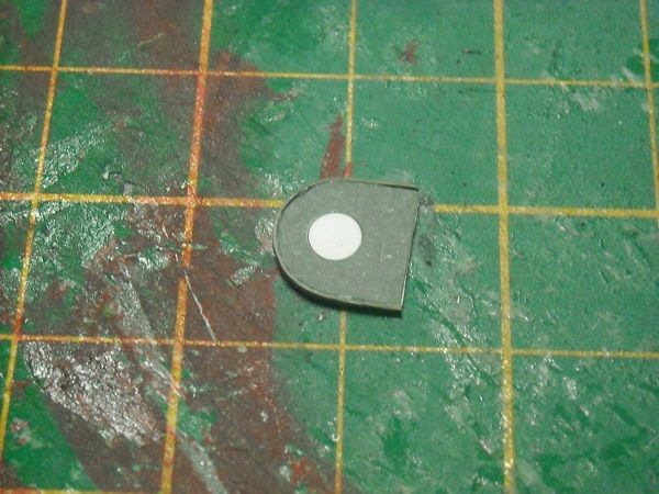 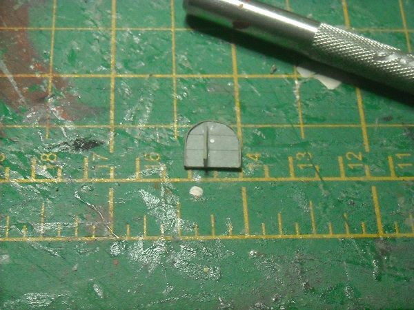 Once it was all dry I glued the column on the platform and then the platform against the side of the tower and on top of the column. 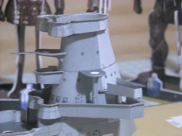 As they say it, job done! But looking ath the conning tower, not a lot is left of the seemingly streamlined tower we started off with. In fact, this conning tower reminds me a lot of the control areas of the German pocket battleships, ships not known for their good looks. Oh well, I guess the grandfather of Laurence Llewelyn Bowen didn't do cruisers. But until the next time! Adrie 'Where to glue or where not to glue, that is the question'
Building: Hr. Ms. de Ruyter (card), Retourschip Batavia (Revell), HMS Surprise (De Agostini)
Built (and sunk): Too many to list
|
|
|
|
|
Hi Adrie, Looking good as usual.... I would just have a concern that too many figure would actually detract from all the fine detail you are able to produce on your build.... A few figures maybe strategically placed may be fine.... Maybe place a few on the finished build but not glued down and then see how it would look overall..... All just my opinion of course..... Regards Alan
|
|
|
|
|
Hi Adrie The build is looking great but personally im not sure on the use of figures on any model that small in scale, I have used then on say 1/35 scale and they look ok and do add something. Of course its personal choice and if that's the way you choose then fine by me. I have the 1/200 Bismark in my stash with the MK 1 etch and all the Eduard etch for the above part of which was the inclusion of some pre-painted crew members that Im sure Il never use just because of there size although they are quite clever in there construction and almost 3-d like your paper/card one's. I have included the link so you can have a look see http://www.eduard.com/st...A-guns-1-200.html?cur=1
Just my opinion and in no way wishing to detract from your excelent build diary. regards Andy Current builds:-C57,Zero, Lamborghini Countach, Caldercraft HMS Agamemnon,Robi,R2-D2, MFH Cobra .
|
|
|
Rank: Pro Groups: Registered
Joined: 23/03/2014 Posts: 185 Points: 545 Location: Essex
|
Thanks for your looking in and comments, Alan and Andy. I guess the consensus is with the both of you, and in fact, all that reacted before. So I'll follow the lead and desist. (And be happy with it, don't you worry!) But there is enough to go on with anyway, so let's get cracking! When I said yesterday that I was going to tackle the last section, I was slightly mistaken. There was one set of parts to be done the be placed the the deck next to the conning tower. They are simple parts. 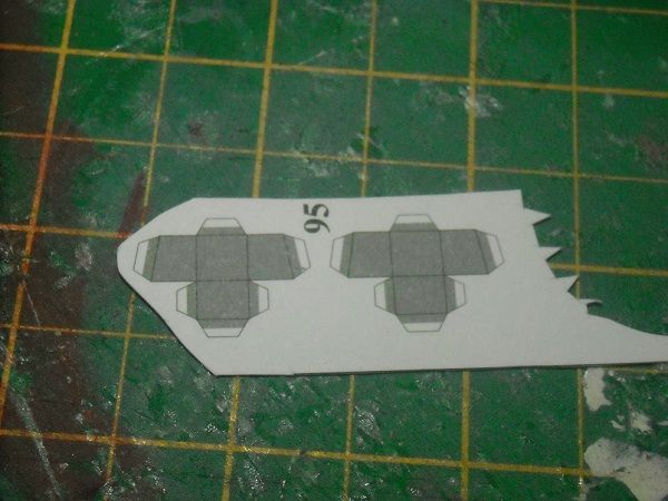 So cutting, scoring, bending and glueing them yielded ...  and glued in place. 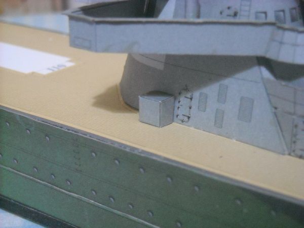 Nothing too taxing there so enough stamina had been left for the last section of the conning tower. 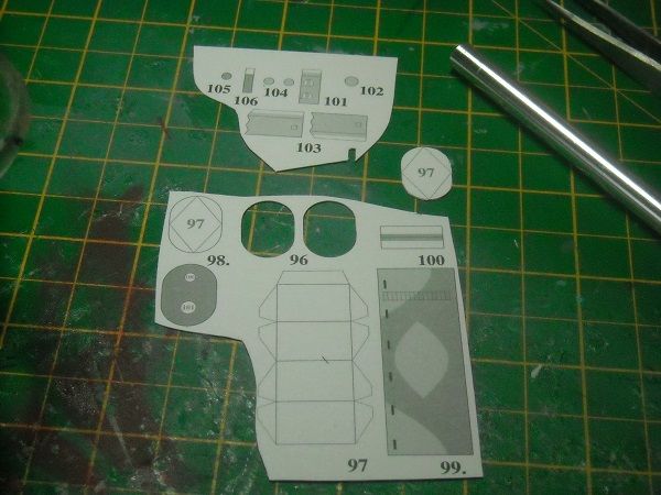 It consists of a framework with a skin and two structures to be placed on top of it, of which one will be the rangefinder. But the frame was constructed first and the skin was bent wih the fingers into a cylinder. 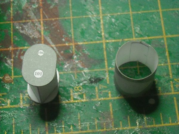 The skin was then slid over the frame and glued in position. 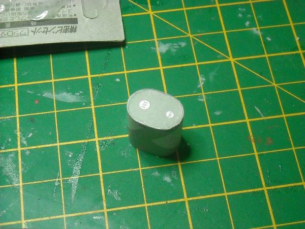 Then the cylinder for the base of the rangefinder was cut out. 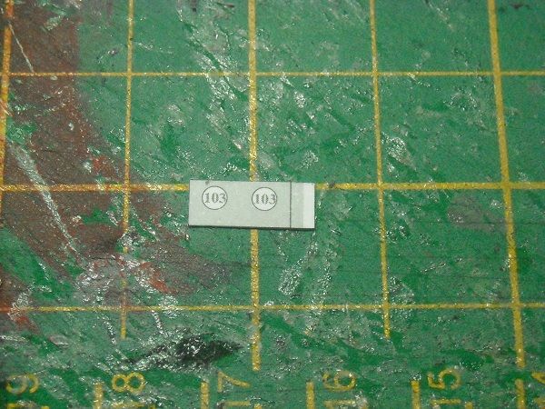 The connecting tab was cut off. 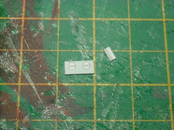 And glued back! 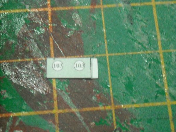 This was done to have the connecting tab lie underneath the cylinderwall so that the wall can be glued together butted which improves the look of the finished cylinder. The 'lid' was glued on and the rangefuinder base was ready to receive its arms. 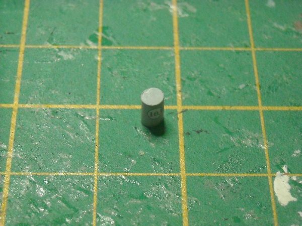 The arms were made from parts 103 and 104. 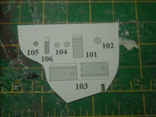 The arms are cylinders with lids. But with these cylinders I have to keep the connecting tabs where they are because of the shape of the left hand side. So the arms were cut out, rolled around a toothpick, then a 1mm brass rod and glued together after which the stabbed out lid was glued in place and the arm was glued against the base. 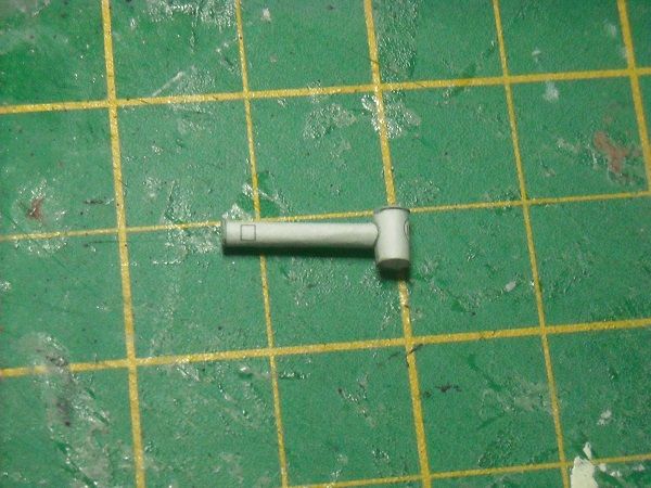 Then the second arm got the same treatment. 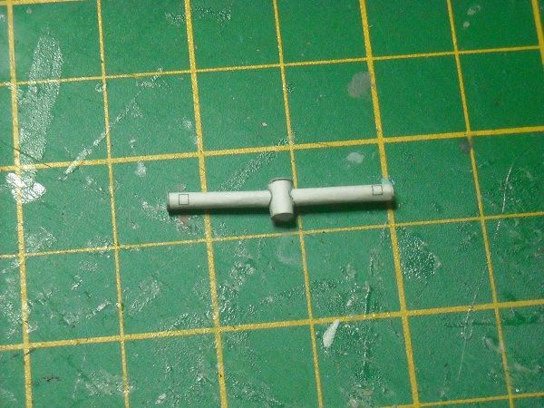 And the rangefinder was glued to the top of the observation position.  I was cooking with gas at this time and started on cutting out the last cylinder parts (105 and 106) until disaster struck! My trusty lamp gave up the ghost and suddenly I was plunged in darkness. Luckily I had a spare light in the bedroom, which gives off a hideous yellow light, but it will have to do for the moment.  But when I got back to the model I could not find the cylinder part that I had cut out anywhere! I guess the carpet gremlins had a new victim! Luckily a toothpick had about the right diameter so a quick splash of paint and cutting it to the right dimensions and hey presto, a replacement cylinder! It was a little bit on the small size but not enough to need extensive surgery. So I had no hesitation to offer up the ersatz part where required.  The observation post was then glued in place and there was the completed conning tower!   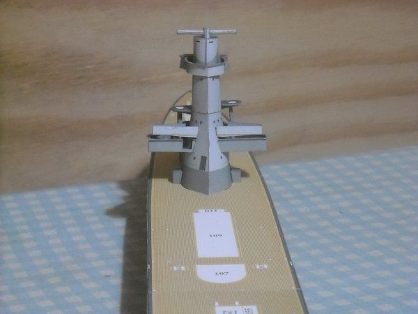 And with that I declare this build section completed! And now I'm off to claim my well earned beer, if you don't mind! And even if you do, I'm going to have one. Until the next time, my faithful followers! Adrie. 'Where to glue or where not to glue, that is the question'
Building: Hr. Ms. de Ruyter (card), Retourschip Batavia (Revell), HMS Surprise (De Agostini)
Built (and sunk): Too many to list
|
|
|
|
Guest (5)
|
 US
US

