|
|
 Rank: Vice-Master   Groups: Registered
Joined: 05/03/2015 Posts: 561 Points: 1,713 Location: South Carolina
|
Very nice comparison bro. I've got Tony's 3D turret on order and waiting for it to come in to get a good comparison myself. Like what you've done so far! Keep it up!
|
|
|
 Rank: Amateur Level 1 Groups: Registered
Joined: 09/01/2016 Posts: 31 Points: 93 Location: UK
|
Nice work on the Turrets :) Question Myawn Did you cut 1 strip of EL Tape multiple times to make the several short lengths to cover each set of scones. If you did which EL Tape did you buy ? , looking at the EL Tape I have it is not possible, after cutting it, to add your own connectors to the tape due to its design. I assume you are driving them all off 1 invertor ? On the WorkBench : DeAg Millennium Falcon , Deag R2-D2
To Build : various 1/72 , 1/32 WW II Military Planes
|
|
|
Rank: Amateur Level 1 Groups: Registered
Joined: 20/07/2015 Posts: 35 Points: 108 Location: Marietta, GA, USA
|
rj1265 wrote:Nice work on the Turrets :)
Did you cut 1 strip of EL Tape multiple times to make the several short lengths to cover each set of scones. If you did which EL Tape did you buy ? , looking at the EL Tape I have it is not possible, after cutting it, to add your own connectors to the tape due to its design.
I assume you are driving them all off 1 invertor ?
The EL tape (and panels) I bought are from Adafruit. They come pre-wired with connectors at each end, so you can cut it into two usable pieces and whatever 'middle' section is left over is unpowered unless you figure out how to do your own connectors. I found a pretty clever (i think) way to wind a single length of EL tape around the larger corridors (main curved corridor and the straight cockpit access corridor). So I only needed one EL tape on that side, and two EL panels that were used for under flooring (one piece for the curved section, one for the straight section). Adafruit sells a 4-1 'Y' type connector so these three (2 panels, 1 tape) are grouped onto a single wire that will run to the inverter. On the shorter (port) side I have one EL panel (under floor) and two EL tapes (sconces), so again 3 wires that go into a 4-1 'Y' to give me a second wire that runs to the inverter. The inverter supports up to 4 connections so I still have capacity to add more -- plan to do something under the hold maintenance pits but haven't rigged that up yet. I haven't yet figured out where the inverter will eventually go -- if it will be outside or inside the model. I think it may end up outside, if I can route the wire to the inverter and the power for the available/optional external AC adapter through the same hull opening provided for the AC adapter.
|
|
|
Rank: Amateur Level 1 Groups: Registered
Joined: 09/01/2016 Posts: 31 Points: 93 Location: UK
|
Thank you, that is very helpful :) , I have seen several articles on cutting EL Tape and adding your own connectors, but none of them would work with the EL Tape I have, I will have a look at the Adafruit tape. I have led strips under floor and will be using EL Tape for the Scones - I think it gives a 'softer glow' , and I didn't fancy wiring up 22 led's ,1 for each scone :) On the WorkBench : DeAg Millennium Falcon , Deag R2-D2
To Build : various 1/72 , 1/32 WW II Military Planes
|
|
|
Rank: Amateur Level 1 Groups: Registered
Joined: 20/07/2015 Posts: 35 Points: 108 Location: Marietta, GA, USA
|
Haven't posted for a while because it's mostly been assembling the upper frame -- nothing too unique or interesting. But I did finish painting the bottom hull so I'll attach a photo of that, along with the current overall state of the hull building. I've got a couple of questions about wiring & lighting that I haven't seen anyone address .. would appreciate advice if anybody has thoughts on these. First question - I've done the ParaGraphix turret interiors, which should be lit from several directions (as opposed to the single LED light for the stock parts). I haven't figured out where would be a good place to attach lights - I'll probably go with the small SMD leds, which worked well for me in the cockpit and hold. But it doesn't appear there's any convenient place to mount these that would then be pointing back at the turrets. Anyone else working with these parts come up with a good answer? Second question - I've used EL panels and tape for lighting in the corridors, and plan to add a bit more surrounding the hold maintenance pits when it comes time to install that. The EL requires a special inverter, so I won't be able to run it (AFAIK) off the supplied board. I think this gives me a couple of possibilities: Option 1 - use an AC adapter for the EL wire, and run the wire in through the provided hull opening for the future-optional AC adapter for the model. (I do plan to buy & use the AC adapter for the model -- so I was thinking that if it did not use the supplied rubber grommet / seal for the opening, I could run both AC wires side by side through the opening. Option 2 - Since I'm planning to use AC for the main model power supply, I don't need the battery pack. It looks like the battery pack for the EL wire would fit into the space provided for the main battery pack. I'm not sure the wires are long enough so splicing in an extension may be necessary in that case. I've ordered Chris Holland's landing light set, so when that arrives I should have something new to post some pictures of. I just this month received the circuit board shipment so it seems to be a good time to be figuring out the power strategy. Here's the painted lower hull:  Here's the lower hull inside (with light blocking applied) and the current frame progress for the upper: 
|
|
|
 Rank: Pro Groups: Registered
Joined: 08/03/2015 Posts: 154 Points: 435 Location: New Jersey
|
Very nice so far. I also ordered Chris' light kit. Mine should be shipping any day. Cant wait to see how it looks installed. My current builds: The Millennium Falcon, Suzuki GSX 1300R Hayabusa, Ford Mustang Shelby
|
|
|
|
|
Looking very nice indead, I like what you have done so far. With regards to the turret interior, I’m using the supplied one, that I have modified. The LED bulb supplied that fits at the top, I have replaced and put a blue bulb in and blacked out the front part, so it only shine towards the rear, giving a more ambient light effect. I have also fitted fiber optic cables to the side walls, some blinking, which also gives of light to the area. I am also using EL wire beneath the hold area flooring, which as you say needs to run off an inverter. I have a 9v inverter and will run this off the hold area wiring loom, which will run through a AC 9v power supply, I plan to utilise the supplied board for this, along with the landing lights I have already mounted in the bottom hull. Looks great, keep up the good work. Mark
|
|
|
Rank: Pro Groups: Registered
Joined: 30/04/2015 Posts: 263 Points: 795 Location: Los Angeles
|
I'll be using a small LED strip to light my turret. I'm still waiting to see how it all fits together though to see exactly where lights can be positioned for lighting. I have thoughts on how to attach, but at this point don't completely know about the room.
|
|
|
Rank: Amateur Level 1 Groups: Registered
Joined: 20/07/2015 Posts: 35 Points: 108 Location: Marietta, GA, USA
|
It's been a while since I've posted, as things have been mostly by-the-book for a while. But this month (Month 23 for me) I got the supports for the cargo hold and corridors, which means I can finish up those parts. I haven't installed the corridors yet, and my initial attempt at turret lighting was unsatisfactory so I'm waiting on more LEDs to arrive so I can upgrade that. But I've quite happy with the way the hold pits turned out so I thought I'd share. I'm using the Paragraphix hold floor kit, which means I've got removable pit covers for both pits. On the front pit, I'm leaving the pit closed and faking it; the rear pit will be open and have a bit of depth to it. Here I've completed laying out the route for the lighting, temporarily supporting it with a piece of cardboard where it extends past the edge of the base. 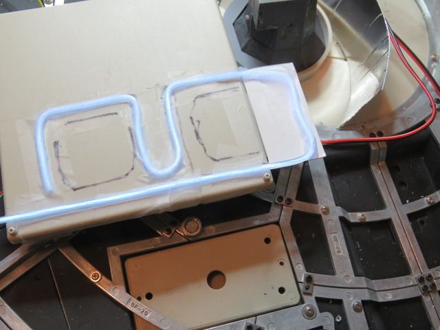 I realized the cutaway section of floor could be lowered and used as the bottom of the pit Here's the cutaway portion before surgery 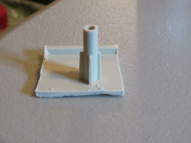 Here the mount has been removed and cut roughly in half, and the bottom reinstalled.  Here the cutaway section of floor has been placed on its peg ... it's not very stable and later I'll add some styrene bracing.  Here's how it looks with both parts of the support installed. I've also used a Dremel to cut a groove in the floor where the EL wire will be routed; hot glue will be used to hold it in place.  In this picture, I've added the pit interior. This is two pieces of side paneling from a Revell Falcon kit. This was going to be it, but later I decided it needed a pipe. 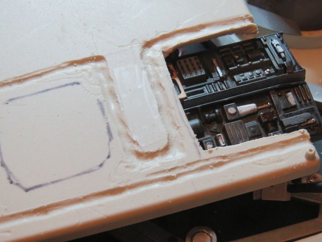 Here I've glued down a picture (colson in the forum here supplied this from a screen capture) of the pit for the front fake pit, and the rear pit is in place but not yet stabilized (so it's definitely tilting to the rear). I added a pipe made from a piece of wooden dowel and some pinstriping tape -- I think this really improves upon having just the kitbashed parts. The EL wire has enough stiffness that the cardboard support was unnecessary. 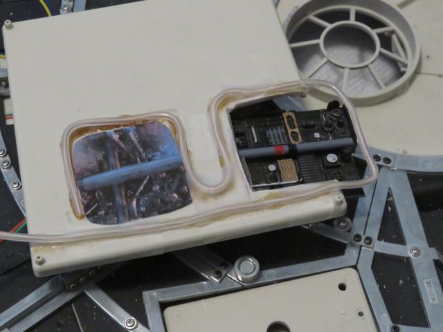 The bracing on the bottom of the floor interfered with the EL wire so it had to go. 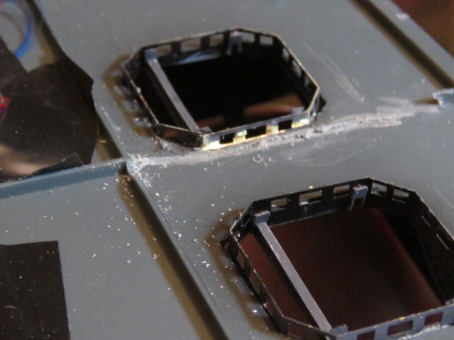 Here it's all coming together - support beams reinstalled for the pits, both pits are now done and I just need to cover up the front one. 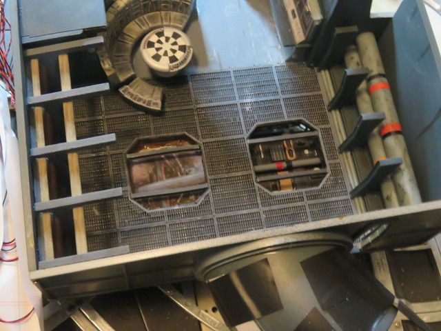 And here with the cover in place for the front. I have some barrels and other parts to go into the hold, and when the starboard corridors get installed I'll hook up the lighting there. But this is it for now. 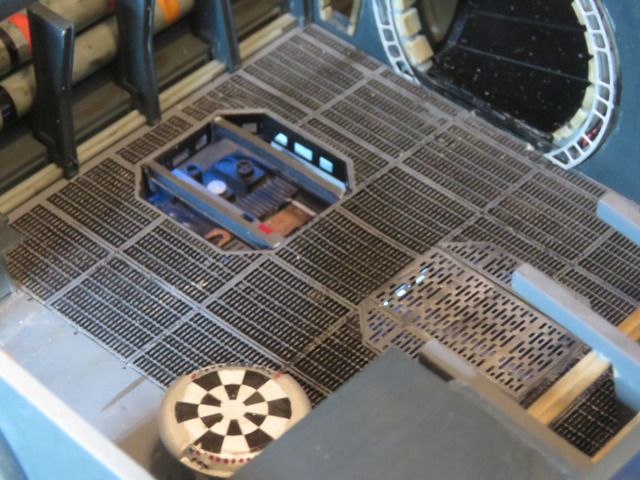 In this shot the hold floor was just a little out of place, I needed to move it a bit and then add a styrene support. (Didn't realize it looking at the real model, only when I looked at the picture did I see the problem! ) 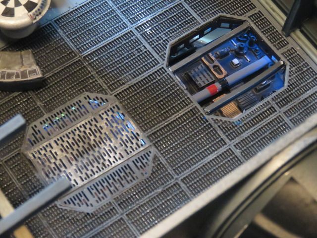
|
|
|
|
|
Looks excellent, great work. 
|
|
|
 Rank: Super-Elite     Groups: Registered
Joined: 27/01/2014 Posts: 5,060 Points: 14,980
|
It looks like a lot of work but the end result is very nice  Job well done 
|
|
|
Rank: Pro  Groups: Registered
Joined: 13/05/2016 Posts: 130 Points: 386 Location: Murrieta, CA (USA)
|
Very nice work working on my cargo hold at this time. Put some of the fiber optics in the Nav Computer need to order the .5mm fiber for the remaining lights. Using the Nav computer from shapeways. Received the new bunk from shapeways need to paint and add fiber optics to it. Still thinking about the circular couch and the table considering shapeways parts for these as well. Make things as simple as possible but not simpler... - Albert Einstein
|
|
|
Rank: Amateur Level 1 Groups: Registered
Joined: 20/07/2015 Posts: 35 Points: 108 Location: Marietta, GA, USA
|
I have more pictures I hope to upload soon, but I had a question first. Has anyone come up with a good solution for concealing the power adapter?
The good news is that I was concerned that some of my added lights were pretty dim running off the battery box, but when I ordered the DeAg official power adapter and switched to using that, everything is burning bright. So it appears that the adapter puts out more amperage than the battery box, even with fresh batteries (I think the adapter is 1 amp -- from memory I thought the battery box was about .75A.
I looked on Shapeways, as I thought I remembered there being a 'power station' that could conceal the adapter. I saw that Tony had something but it isn't really set up to route a power cord through it -- I could always drill my own openings and use that, but I wasn't sure if there was something I was missing as far as having something made specifically for use with the power adapter.
If someone already covered this in a build diary and I missed it I apologize -- I do try to look at everything but that doesn't mean I'll remember it all :-).
Thanks
Mike
|
|
|
Rank: Pro Groups: Registered
Joined: 30/04/2015 Posts: 263 Points: 795 Location: Los Angeles
|
I will have my power running up along side my mount going in through the lower gunner port. I'm not using the hole supplied with the kit. If I were able to run it inside the mount, I would, but it doesn't work that way. But it'll be tightly secured to the mount and pretty much unnoticeable. You can see the mount it my #414 post.
|
|
|
Rank: Amateur Level 1 Groups: Registered
Joined: 20/07/2015 Posts: 35 Points: 108 Location: Marietta, GA, USA
|
colson wrote:I will have my power running up along side my mount going in through the lower gunner port. I'm not using the hole supplied with the kit. If I were able to run it inside the mount, I would, but it doesn't work that way. But it'll be tightly secured to the mount and pretty much unnoticeable. You can see the mount it my #414 post. Very impressed with your mounting solution. I had started out thinking I'd go with a wall mount, but toward the end switched around to thinking I'll display the ship on its landing gear. I hadn't though about relocating the wiring. If I don't come up with a solution I like with the current power socket location, I might think about running the wire up the back side of one of the landing gear, where it would be fairly well concealed.
|
|
|
Rank: Amateur Level 1 Groups: Registered
Joined: 09/01/2016 Posts: 31 Points: 93 Location: UK
|
myawn wrote:colson wrote:I will have my power running up along side my mount going in through the lower gunner port. I'm not using the hole supplied with the kit. If I were able to run it inside the mount, I would, but it doesn't work that way. But it'll be tightly secured to the mount and pretty much unnoticeable. You can see the mount it my #414 post. Very impressed with your mounting solution. I had started out thinking I'd go with a wall mount, but toward the end switched around to thinking I'll display the ship on its landing gear. I hadn't though about relocating the wiring. If I don't come up with a solution I like with the current power socket location, I might think about running the wire up the back side of one of the landing gear, where it would be fairly well concealed. I am going to display mine on its landing legs - watching ESB there are lots of items of 'gear / stuff' (I think is best way to describe it ) on the hanger floor at Hoth Base - I am considering scratch building a 'generator' that supplies ground power to the Falcon and take my power in through that route or as you say hide it up one of the landing legs. On the WorkBench : DeAg Millennium Falcon , Deag R2-D2
To Build : various 1/72 , 1/32 WW II Military Planes
|
|
|
Rank: Pro Groups: Registered
Joined: 30/04/2015 Posts: 263 Points: 795 Location: Los Angeles
|
myawn wrote:If I don't come up with a solution I like with the current power socket location, I might think about running the wire up the back side of one of the landing gear, where it would be fairly well concealed. There was a point I had thought about displaying on the landing gear, and that was going to be my solution. Running power up the landing gear to conceal as much as possible.
|
|
|
Rank: Pro Groups: Registered
Joined: 13/05/2016 Posts: 130 Points: 386 Location: Murrieta, CA (USA)
|
colson wrote:myawn wrote:If I don't come up with a solution I like with the current power socket location, I might think about running the wire up the back side of one of the landing gear, where it would be fairly well concealed. There was a point I had thought about displaying on the landing gear, and that was going to be my solution. Running power up the landing gear to conceal as much as possible. I was thinking about the power for the falcon, maybe make the cord look like a fuel line, then it just looks like it is being refueled. Make things as simple as possible but not simpler... - Albert Einstein
|
|
|
Rank: Pro Groups: Registered
Joined: 30/04/2015 Posts: 263 Points: 795 Location: Los Angeles
|
Bill-Devine wrote:I was thinking about the power for the falcon, maybe make the cord look like a fuel line, then it just looks like it is being refueled. That could look pretty cool too. Add some greeblies to the connector end.
|
|
|
|
Guest (2)
|
 US
US

