|
|
 Rank: Semi-Pro Level 2   Groups: Registered
Joined: 11/01/2017 Posts: 89 Points: 259 Location: Lancashire, UK
|
This is the new, first release from Agora Models, in 1:8. Model features: Functioning headlamps and taillights Engine sound when the accelorator pedal is pushed Stop lights go on when brake pedal is pushed Steering wheel operates front wheels Opening doors, hood and trunk Genuine horn sound, by pushing the center of the steering wheel Colour matched to original Dupont paint codes Replica of the Goodyear Thunderbolt tyres Folding rear seats to extend the trunk PACK 1
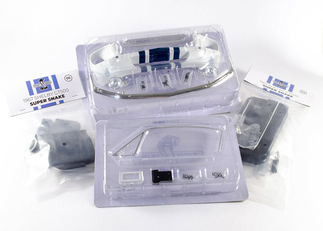 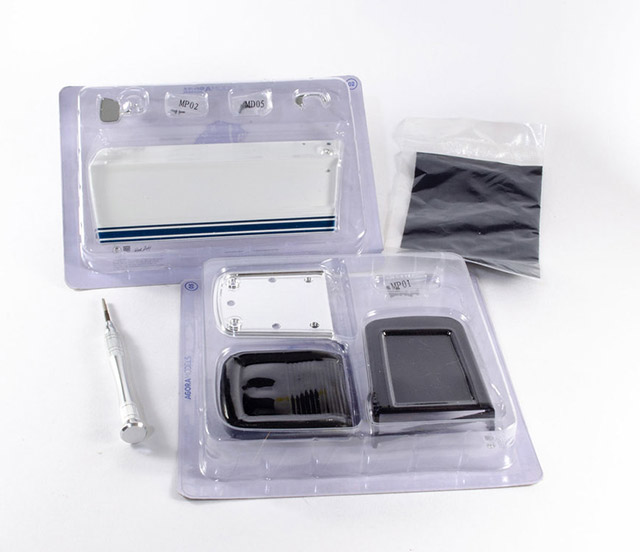 I've only recently started building 1:8 cars as part-works, and I have to say that this model is gorgeous. The parts are seriously high quality with everything fitting perfectly so far, and the paint finish is immaculate. The colour info sheet is excellent and the inclusion of a polishing cloth is a nice touch does help at the end of a session when you pop things away until the next pack....and especially for taking photos for a build log. Things start nice and easy with the front fascia and bottom grille 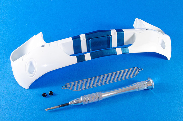 The photo-etch grill is nice and sturdy and fits into the interior of the fascia, secured by a couple of screws. There is a little side-side movement so make sure the alignment looks even and then tighten up those screws. 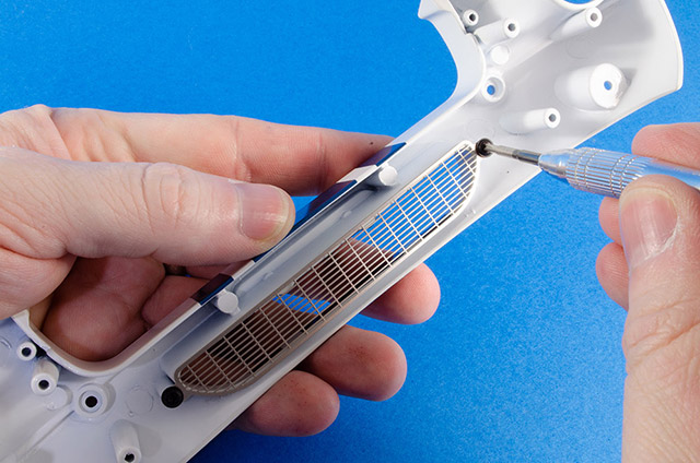 Next up is the bumper. This fits with the pips on the upper side and the recess on the lower side. Pop this into place and secure with the supplied screws. 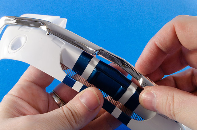 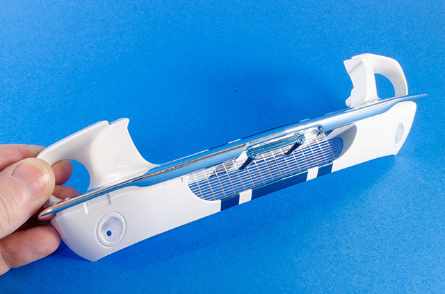 The headlight units are pre-made, and marked as 'L' and 'R' on the rear side. Take each in turn and slot into position from the front of the fascia. 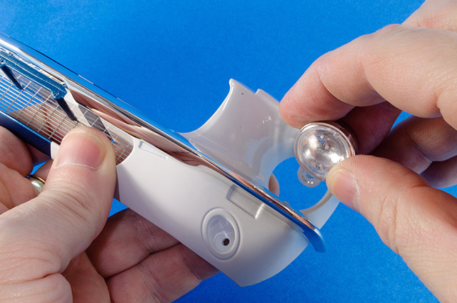 Flip the fascia over and secure with screws. Make sure these are nice and tight. 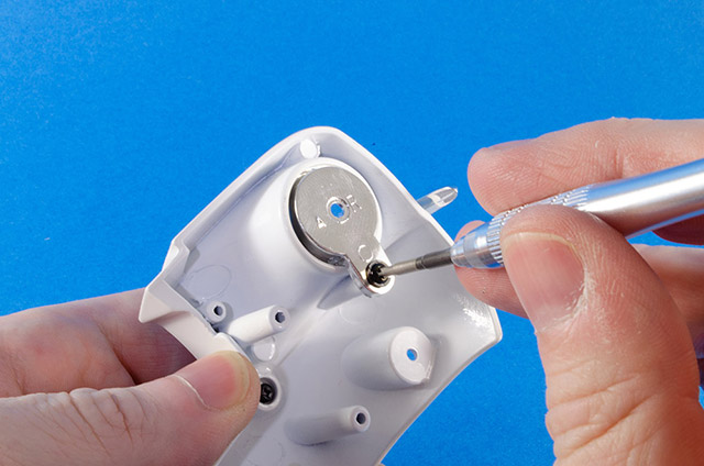 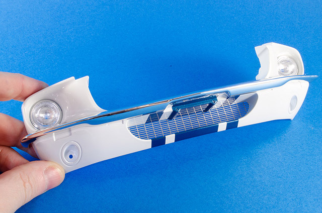 Now, it's the turn of the left hand door, also with its famous livery. We now need to fit the mirror unit. 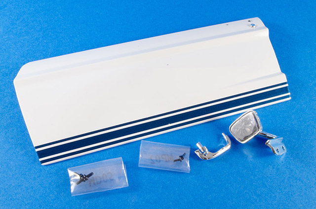 The mirror unit has a tab which goes through the slot in the main door panel. 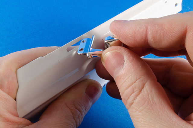 Two screws now secure this from within the door panel. This will pull it up nicely into place. Again, make sure it's tight, and careful not to scratch any paintwork. 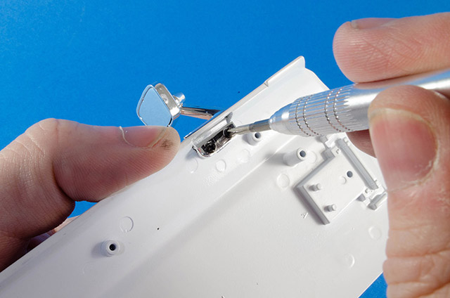 It's now the turn of the door handle. This can only fit into the exterior of the door in one way. 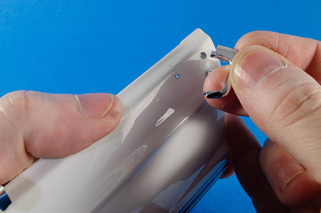 Again, from the interior, secure this with a single small screw. 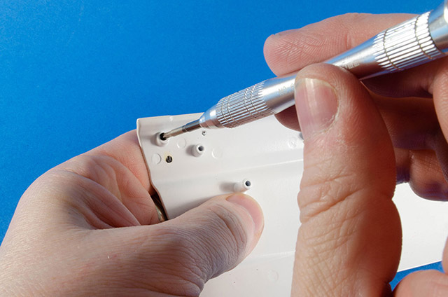 And here is the result. 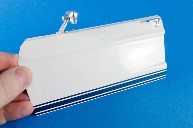 Care needs to be taken over the next stages because you really don't want to damage this beautifully clear part. 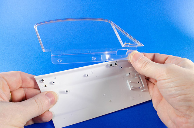 Screw the window unit into place within the door interior, using three screws. 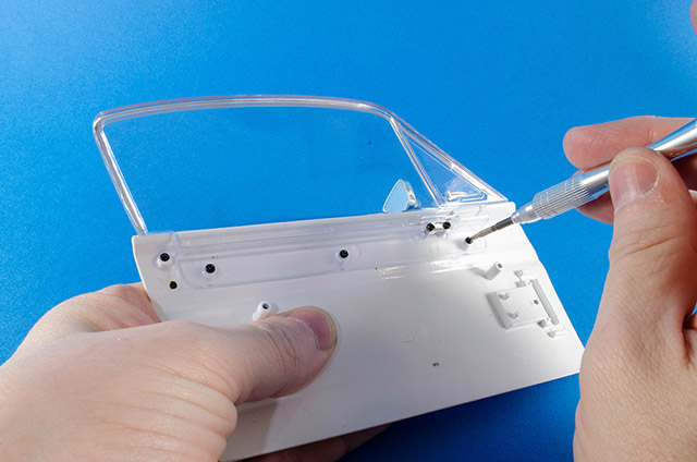 Next, fit the hinge. Note the orientation of this as it's important. 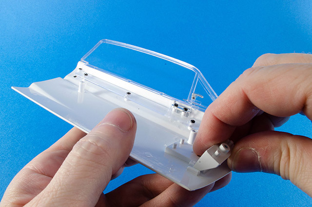 Now fit the retaining plate with the bevel facing upwards. Secure with a screw. 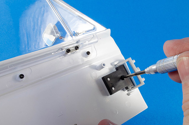 We can now start building the door interior. Take the inside door panel and lower trim strip, and fasten in place with two screws. 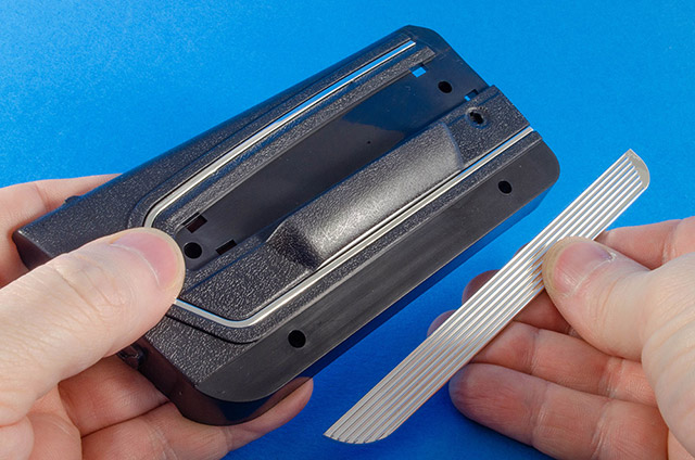 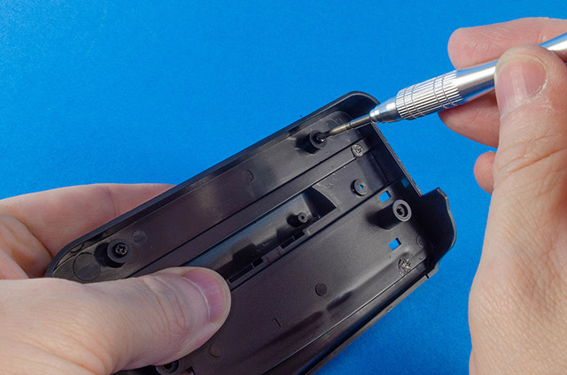 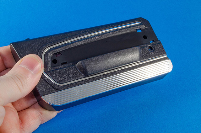 The door handle bracket needs to be orientated in the correct way here. Take the interior door handle and fit it like this. 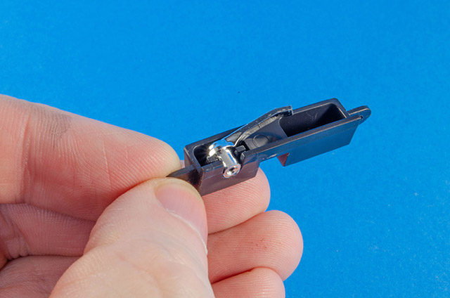 Now fasten the bracket into the back of the door panel, slotting the handle through the hole. Take another screw and screw this into the back of the handle. This will stop it from rocking about. 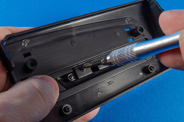 The window crank handle now fits into this recess. This is tabbed so it fits in the correct position. Screw this tightly from behind. 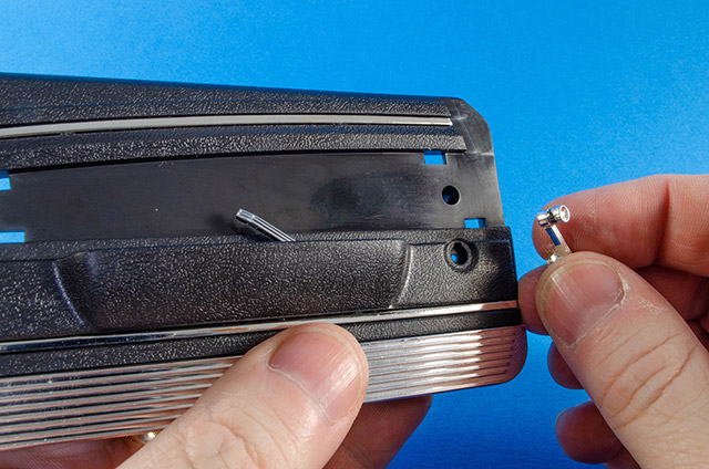 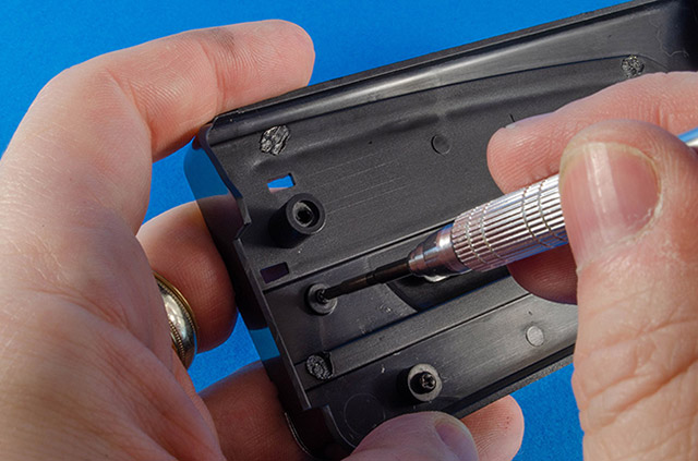 The interior door panel can now be fitted to the inside of the main door, and secured with two screws. 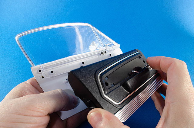 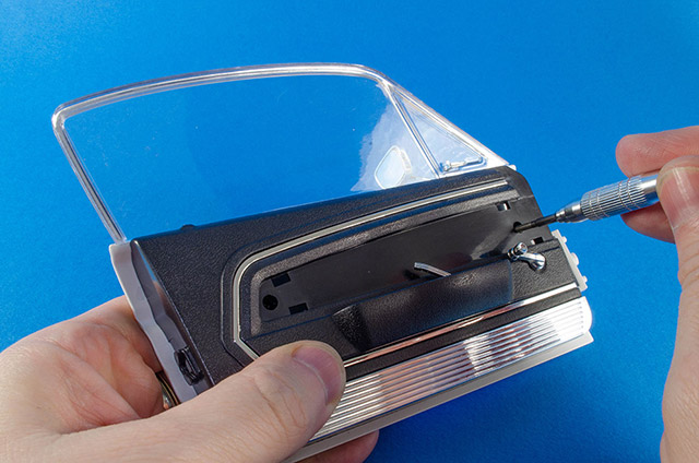 The upper trim strip now fits in place and hides the screw holes. This needs to be fitted carefully so as not to damage the door fittings. 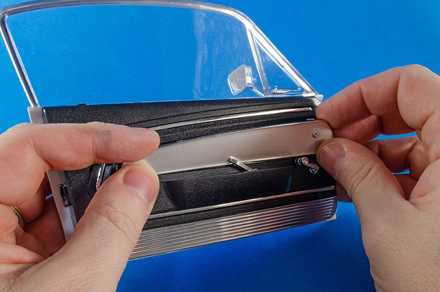 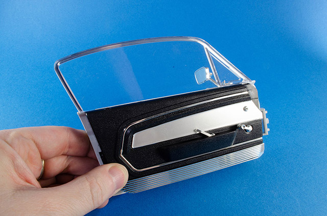 A driver needs somewhere to sit, and this is it. The backrest and backrest frame are now pushed together and secured with four screws. 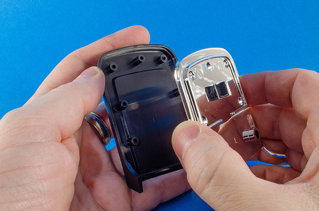 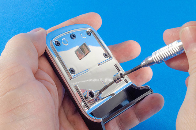 Superglue is now dripped into the three holes in the unit. The instructions say to apply this to the pins, but it's safer to do it this way as the glue can't run anywhere and ruin the parts. 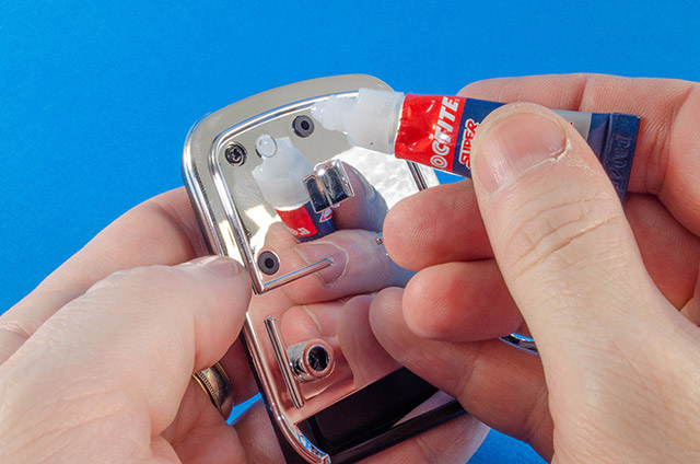 Push the soft plastic upholstery unit into the holes. The tab helps with alignment. 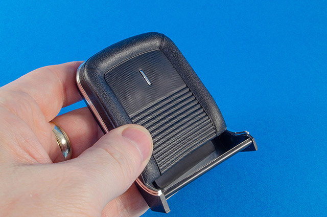 The driver's seat back part now locates to the base. You can easily see how these go together with the channel. 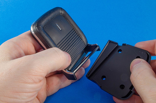 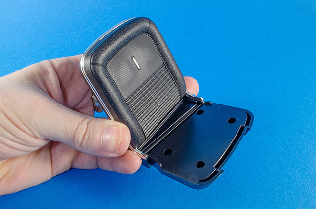 The driver's seat upholstery (with pre-fitted trim) now sits in place over this and is screwed together from underneath. 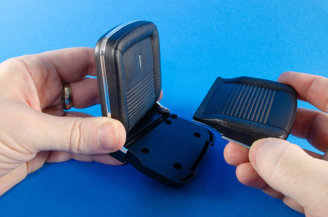 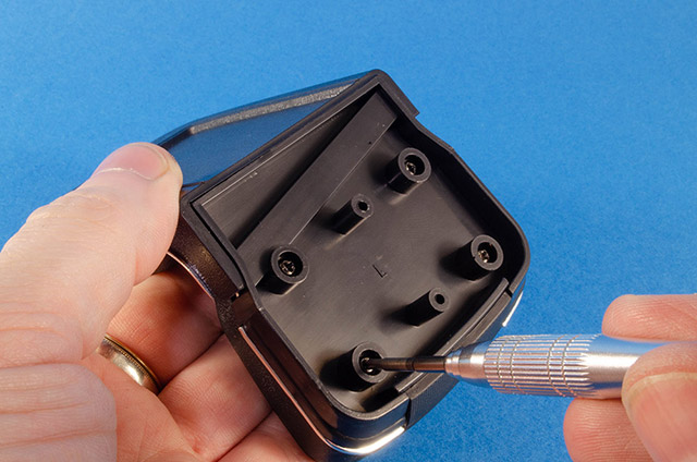 The finished unit looks like this and can also be tilted forward. 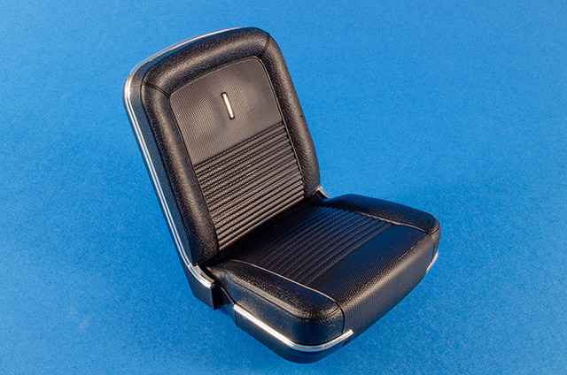 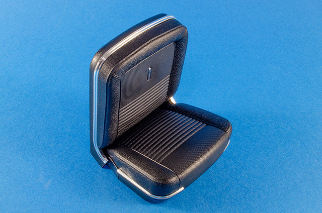 38 Pack 1 is now at completion and I hope to be able to bring Pack 2 to you fairly soon.
|
|
|
 Rank: Vice-Master    Groups: Registered
Joined: 05/03/2017 Posts: 531 Points: 1,710 Location: Midlands, UK
|
Wow, this looks superb! Looks like another model added to my growing build list Building:
Ghostbusters Ecto-1, Ford GT40, Gone in 60 seconds Eleanor mustang, Shelby Cobra
Complete:
R2D2, Red Bull RB7 RC, Battleship Bismarck, Shelby GT500 'super snake'
|
|
|
 Rank: Superelite   Groups: Registered
Joined: 10/05/2010 Posts: 2,608 Points: 7,519 Location: Lincolnshire
|
 Prefer this colour combo to the Modelspace one. Sorry, just like white cars  and as you say, that paintwork looks superb  . Will you be doing any mods or is it 'straight out of the box'? Regards Gray
|
|
|
 Rank: Pro  Groups: Registered, Moderator Joined: 20/01/2013 Posts: 161 Points: 455 Location: Celle, Germany
|
what a great model. Really good. The colors are brilliant. I look forward to continuing to watch you build. Der gesamte Baubericht und alle Fotos unterliegen dem Urheberrecht. Verwendung außerhalb dieses Forums bedürfen schriftlicher Genehmigung. © Levelord
@work: X-Wing,Dodge Charger, MIG-29
Completed: McLaren MP4-23, Hummer H1, RedBull RB7, Easy Rider Bike, Jaguar E-Type, Porsche 911, Ferrari F2004, AMG DTM Mercedes, Ford Mustang, R2-D2, C57, Modellbahn,Rossi Bike,VW Käfer 1303,VW T1 Samba Bus
|
|
|
|
|
Guys, this is a members build diary and not a place to hold a comparison discussion between DeAg and Agora products. If you wish to hold such a discussion then you should start a new topic in the appropriate discussion area. The comparison discussion comments have now been removed from this member’s diary.
Regards
Alan
|
|
|
Rank: Semi-Pro Level 2 Groups: Registered
Joined: 11/01/2017 Posts: 89 Points: 259 Location: Lancashire, UK
|
|
|
|
Rank: Superelite Groups: Registered
Joined: 10/05/2010 Posts: 2,608 Points: 7,519 Location: Lincolnshire
|
The more i see of this build, the more i like it
|
|
|
Rank: Super-Elite Groups: Registered
Joined: 17/12/2013 Posts: 3,982 Points: 11,974 Location: NY, USA
|
looks great James.I am looking forward to your next posts.
Carl
|
|
|
Rank: Administration    Groups: Registered, Administrators, Global Forum Support, Moderator, Forum Support Team, Official Builds Joined: 04/01/2016 Posts: 7,222 Points: 21,973 Location: Northamptonshire, England
|
Great work James, looking forward to your next instalment.  Mark Regards
Markwarren
(Mark) Admin
|
|
|
Rank: Semi-Pro Level 2 Groups: Registered
Joined: 11/01/2017 Posts: 89 Points: 259 Location: Lancashire, UK
|
Ok, onto Pack 3! Let's change that background to white also, as I need to get a new blue sheet and lockdown prevents this! This is a lovely pack goodies because we now get to work on the lower chassis and put together some large parts that give an impression of just how big this 1:8 beauty will be when complete. Quite a bit of work to do here too, and let's face it, many of us haven't much else to do with our time at the moment! 🤣 Stage 15: Rear Main Chassis AssemblyNot much in this packet, but it is pretty significant. Take the rear main chassis part and connect to the fuel tank assembly. As simple as that, but now you can see how this thing is starting to grow, and the fit is superb! 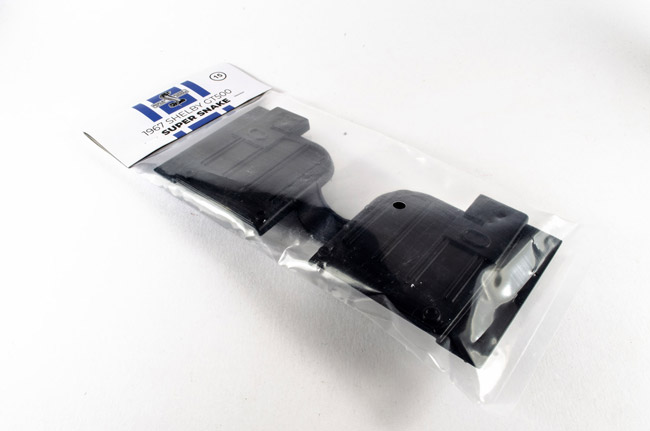 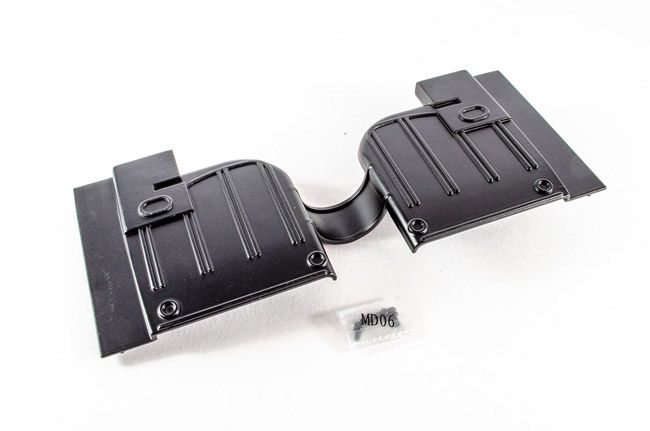 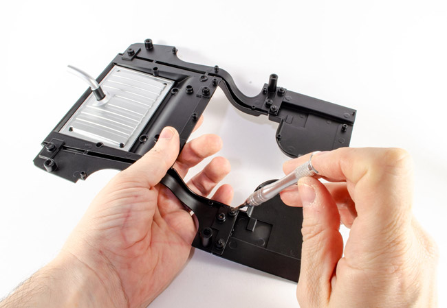 Stage 16: Rear Floor Pan Stage 16: Rear Floor PanAgain, only one part here, but I got 2 packs of screws. Only one of them is used, so the other looks like I can just use for any spares I might need (although the instructions also show the pack, but no use for them). Take the Rear Floor Pan part and fit to the rear chassis. Pretty obvious where this goes. It's simply like fitting a square peg to a square hole, metaphorically speaking. Nine screws hold this in place. 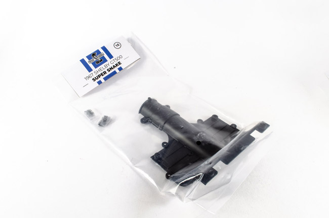 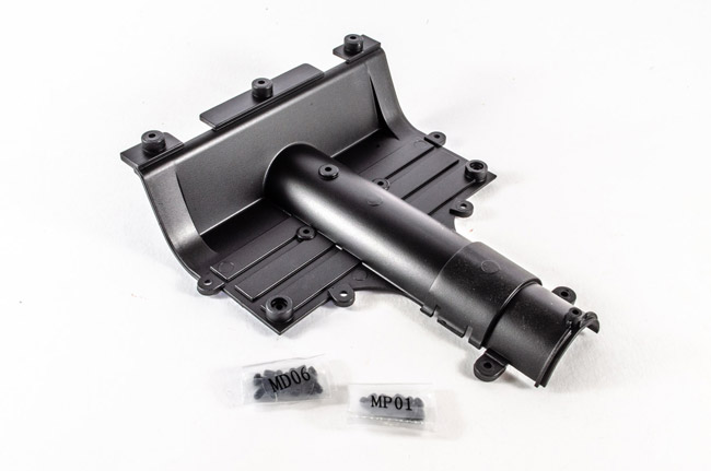 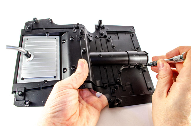 Stage 17: Lower Rear Axle Stage 17: Lower Rear AxleThis pack gives us the differential housing cover and the lower rear axle, plus screws. Take the differential cover and fit two screws into it so they go fully home. This just nests to the outside of the axle. Note the orientation of the differential though. That's pretty crucial. 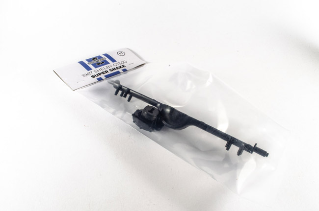 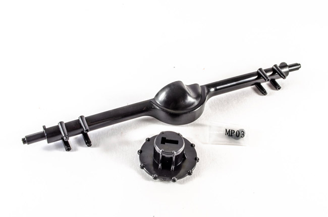 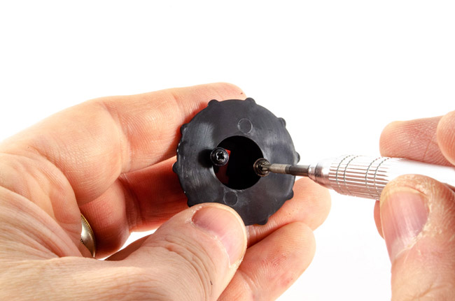 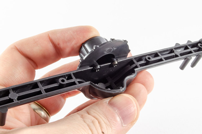 Stage 18: Upper Rear Axle Stage 18: Upper Rear AxleCarrying on from the previous stage, we now get to complete the rear axle using this pack of components. Again, check the orientation of the differential from the previous stage and then fit the upper rear axle. You can clearly see that orientation here. Secure the parts with screws. You can also slip the springs into position too. 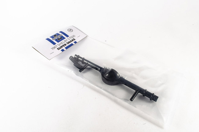 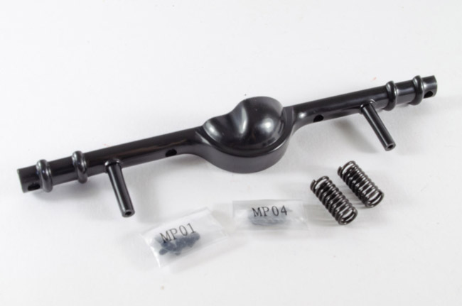 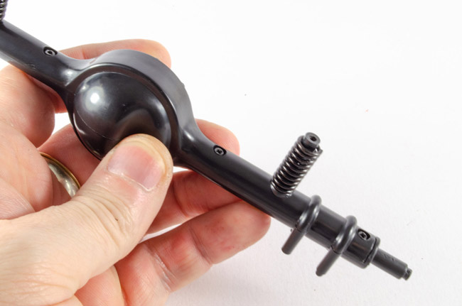 The upper rear axle assembly can now be fitted to the rear chassis. Noting orientation, sit this so the two rods that the springs are sat on, connect to the lower chassis as thus, and then secure with two screws... 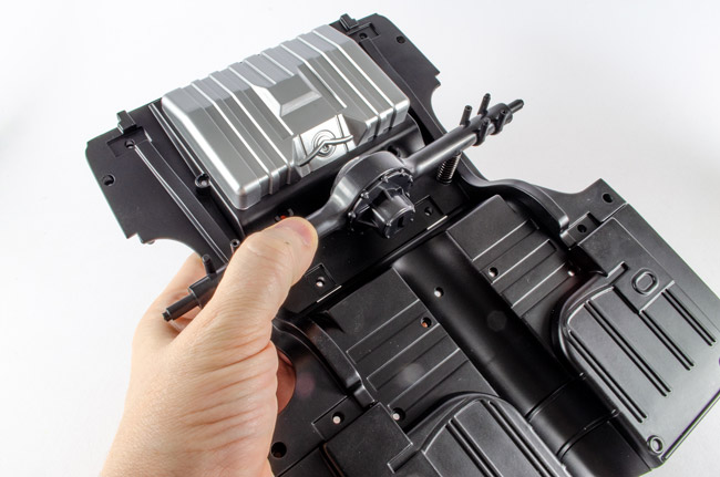 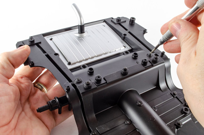 Stage 19: Left Rear Wheel Housing Stage 19: Left Rear Wheel HousingAnother pack with one part, but oh how beautifully it fits! Take the housing and secure to the left side of the lower chassis with three screws. 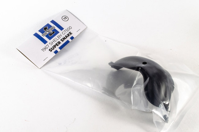 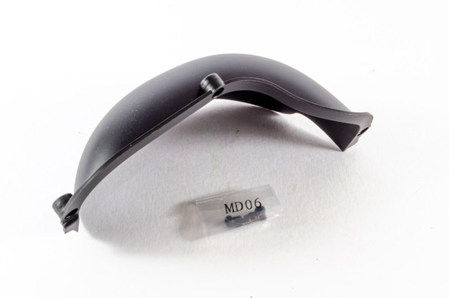 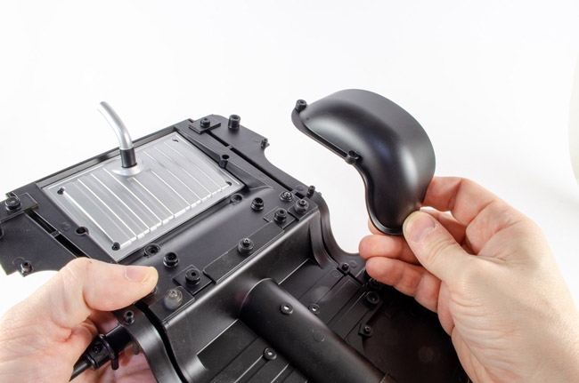 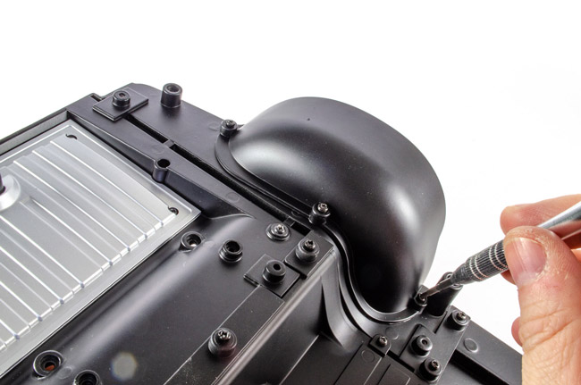 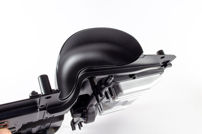 Stage 20: Left Leaf Spring Stage 20: Left Leaf SpringNow, you need to pay attention here to make sure you get the orientation of these vital parts, correct. You'll struggle to disassemble otherwise. These photos should clearly show you how this fits. Note the shape and position of the details on the leaf sprint itself, and be careful not to bend this part as it's a little pliable. Take the front shackle (very different to the rear shackle) and note which side of the leaf spring it fits to. Now push the pin into position to secure. One side of this is serrated, and when you push it fully in, those serrations will bite into the plastic and lock it. Use pliers for this. 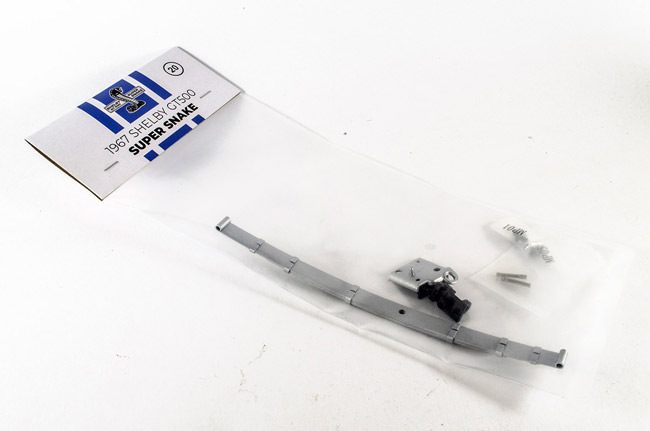 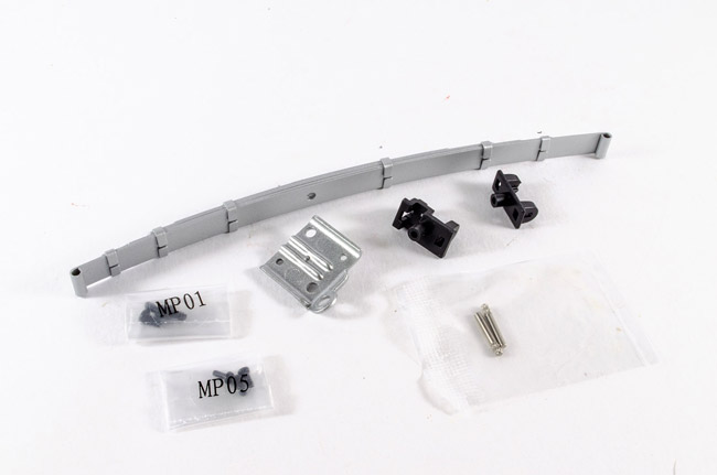 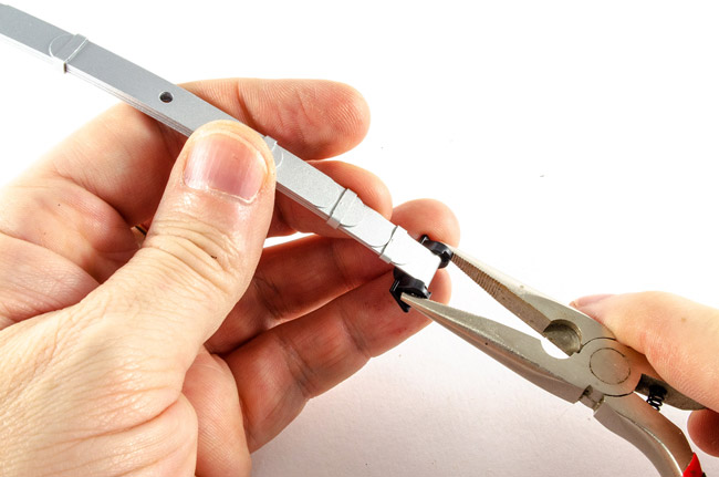 Now do the same for the other side... 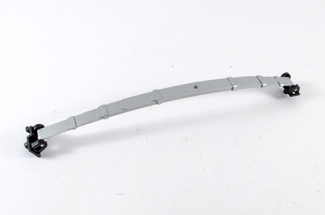 The leaf spring can now be fitted to the lower chassis. Note how those shackles match the underside when they fit. Lastly, the spring plate can be fitted with two screws. 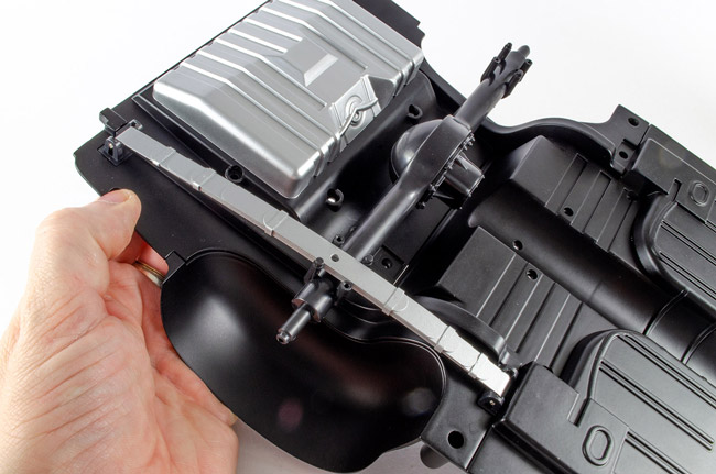 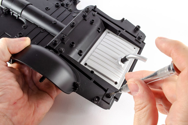 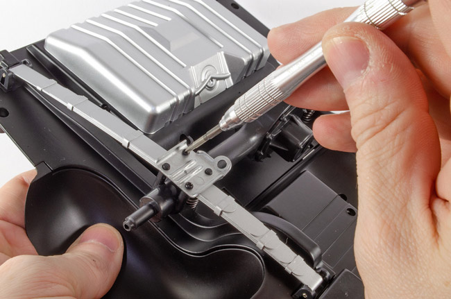 Stages 21 and 22: Right Wheel Housing and Right Leaf Spring Stages 21 and 22: Right Wheel Housing and Right Leaf SpringThe last two packs are the same as the previous two except we now fit these for the right hand side of the lower chassis. 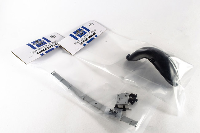 And here's how it all looks when done! More next time! 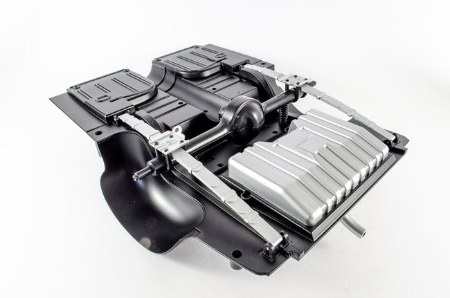
|
|
|
Rank: Pro Groups: Registered
Joined: 25/12/2019 Posts: 218 Points: 659 Location: Manhattan, NY
|
Nice work James! Lockdown really is a bummer, and I could use a couple model supplies myself. I think the pics turned out great with the white sheet though. Happy Modeling! -Dustin
“Details make perfection, and perfection is not a detail.”
-Leonardo Da Vinci
Currently Building:
Porsche 2.7 RS
Currently Collecting
Jaguar E-Type, Ferrari F40, Ferrari 250 GTO, Lamborghini Miura, Ford GT40, Ecto-1, Japanese Zero, Porsche 917, Lancia Stratos
|
|
|
Rank: Semi-Pro Level 2 Groups: Registered
Joined: 11/01/2017 Posts: 89 Points: 259 Location: Lancashire, UK
|
And I can now post up the completed Pack 4!! Pack 4 dropped onto the doormat this week, as the postman legged it quickly in case I gave him coronavirus 😆 Well, I had to make a start, so here we are! Stage 23: Middle ChassisA very simple, single piece packet with some screws, but this really starts to make that chassis grow! This simply bolts to the rear chassis that we just saw in my last post. 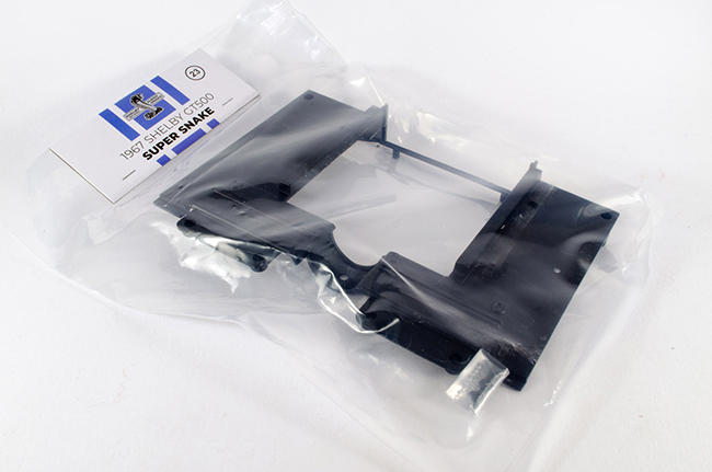 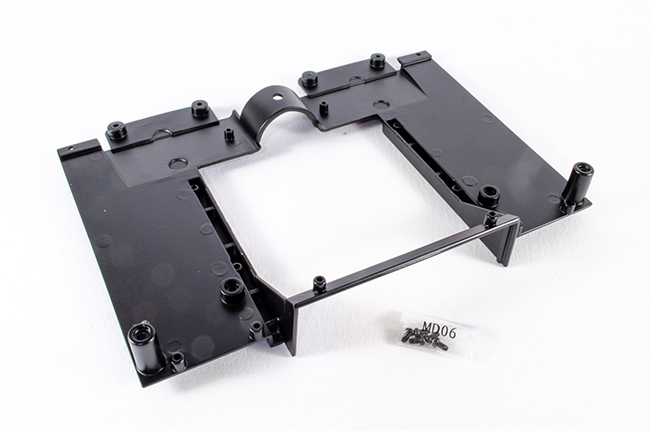 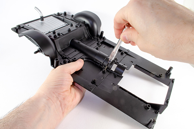 Stage 24: Front Floor Pan Stage 24: Front Floor PanAgain, another simple, one-part pack, and this one fills in that gaping hole in the middle chassis and extends the channel for the driveshaft. What I like about these parts is how precisely they fit...no faffing or manipulation. Just how it should be. 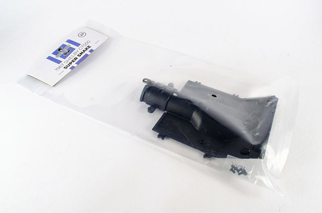 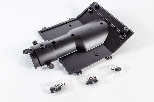 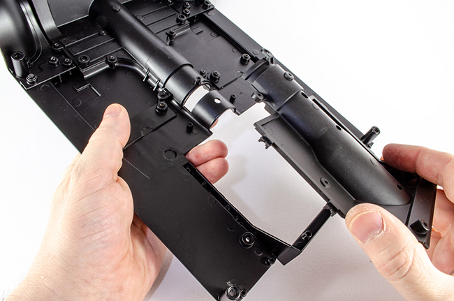 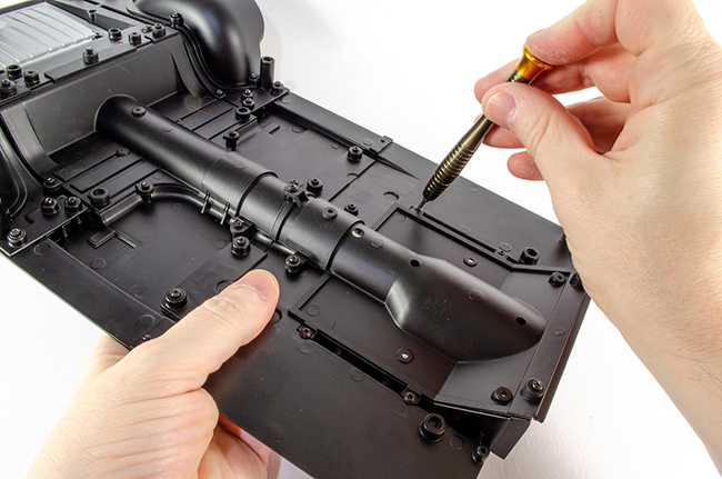 Stage 25: Driveshaft Stage 25: DriveshaftWe can now build that driveshaft and install it. I suppose this is where you'll find if you got the differential cover the right way around 😆. Take the two halves and pop them together. They'll only fit one was as the ends aren't symmetrical. The small MP02 screws are what are used to secure them. Once tightened up (not over-tight!), flip the chassis upside down and slot the tabbed end into the differential, with the two protruding lugs pointing towards the chassis, and then turn the assembly around. Using the other screws, secure the driveshaft securely in place. 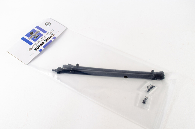 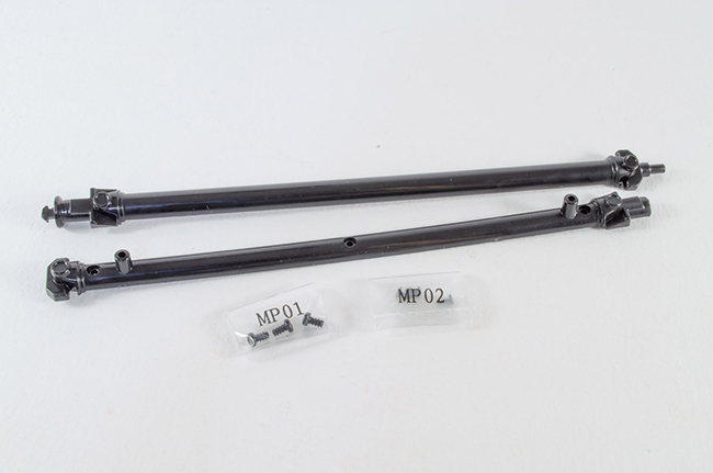 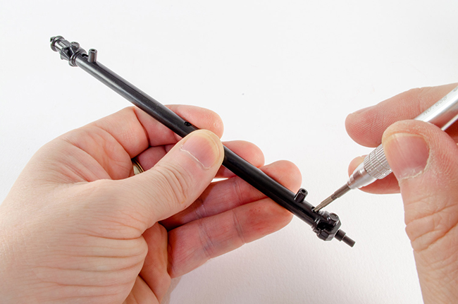 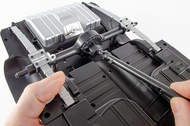 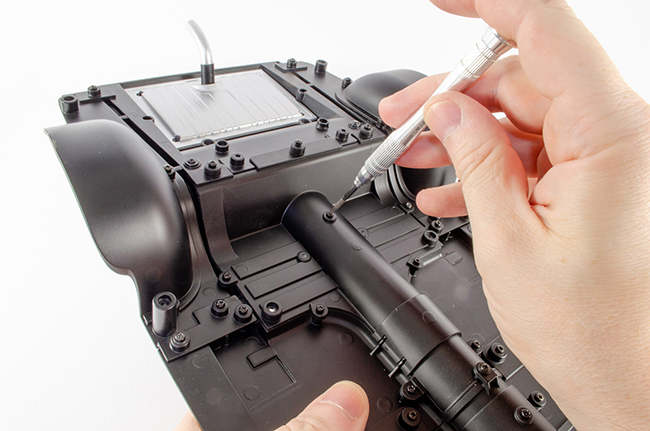 Stage 26: Gearbox and Crossmember Stage 26: Gearbox and CrossmemberSilly me forgot to add the crossmember into the components photo, but you still see me install it. Take the blue gearbox unit and position it as shown. It will only fit one way, so there's no chance of getting it wrong. Flip the chassis over again and secure into position with two screws. Now add the crossmember and again, secure with two screws. 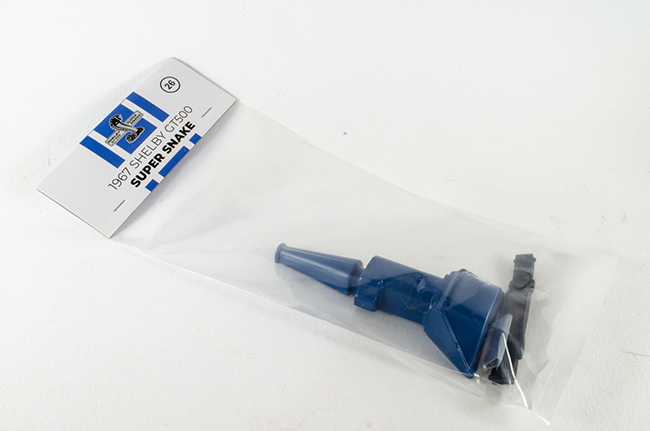 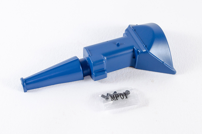 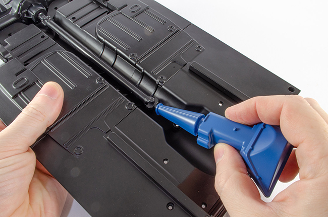 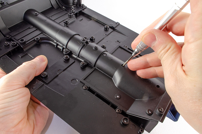 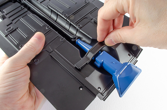 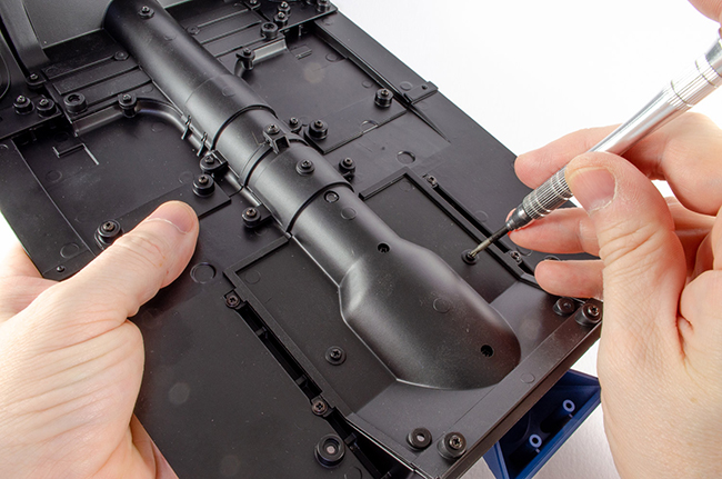 Stage 27: Front Chassis Stage 27: Front ChassisAnother single-part stage, but this now extends the chassis into the full length of the GT500, and it's certainly an impressive beast! This is chunky and heavy metal part too. All that needs to be done is to locate it to the chassis section you already built and then bolt into position as shown.  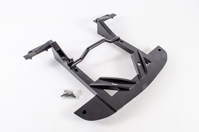 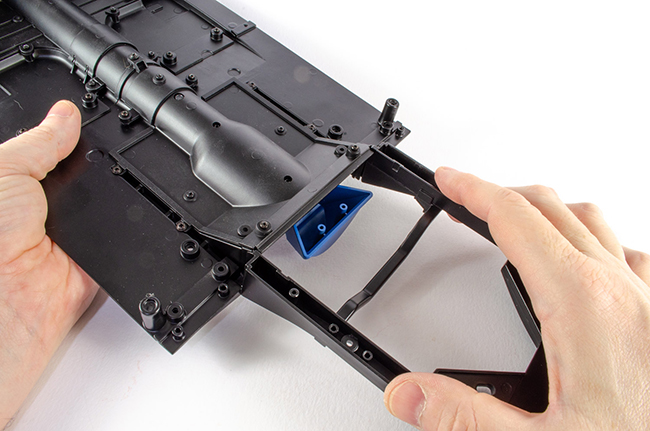 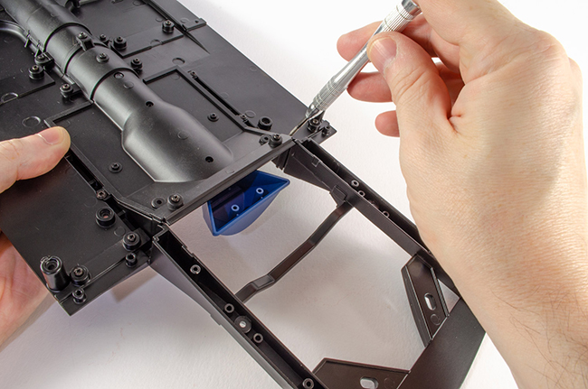 Stage 28: Front Fender Splash Guards Stage 28: Front Fender Splash GuardsOnly two pieces here, and they do exactly what they say on the tin! I found that adding the screws first and then removing them was the best strategy as you can't get a lot of leverage on that screwdriver with the guards right up against it. Be careful handling the chassis now these are fitted as they could be a little fragile. 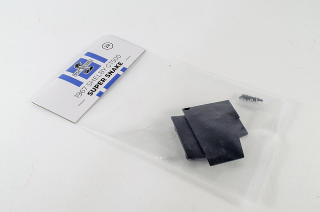 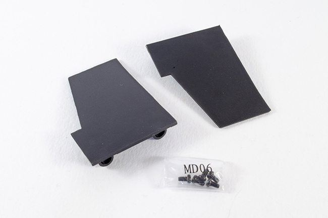 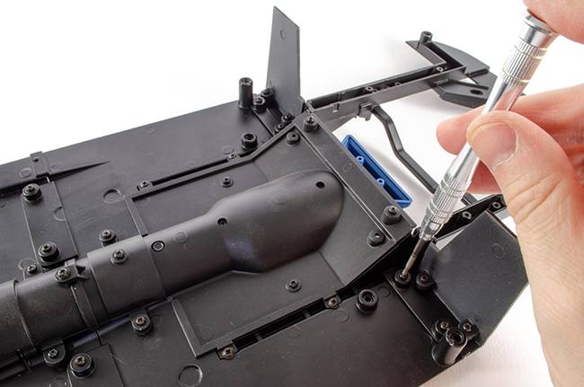 Stage 29: Steering Rods Stage 29: Steering RodsWe can now temporarily put the chassis down as the steering rods are assembled. Quite simply, these three components are bolted together using the MD06 screws. This should not be overtightened as it's a functioning part. I found the screws a little hard to drive in so needed a slightly larger screwdriver with a little more torque. 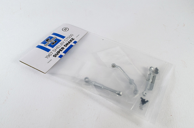 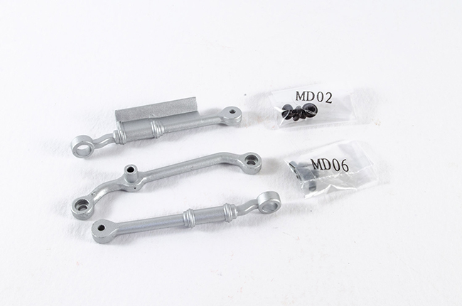 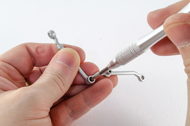 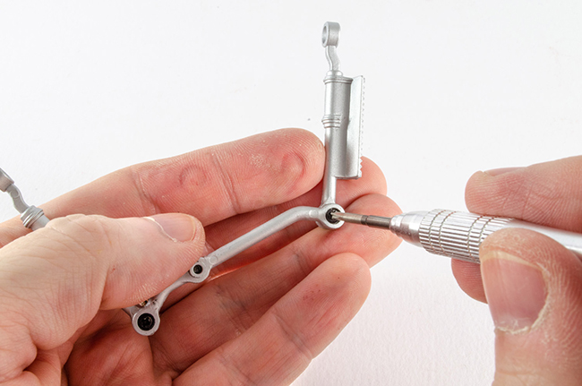 Stage 30: Steering and Suspension Components. Stage 30: Steering and Suspension Components.Whilst the steering rods were in hand, I took the Pitman Arm and bolted this to the assembly I just built. Again, I needed a larger screwdriver to overcome the difficulty I had fitting these together. The suspension arm mounts are then secured to the underside of the chassis via two screws. These are socketed so they won't wobble around. Lastly, the steering gear is also screwed into place. Careful with this as it's plastic and you don't want to strip the threads. 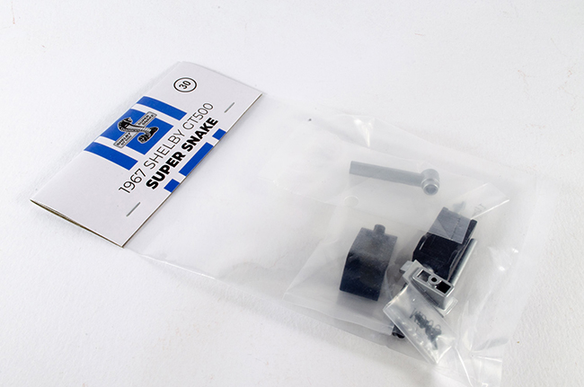 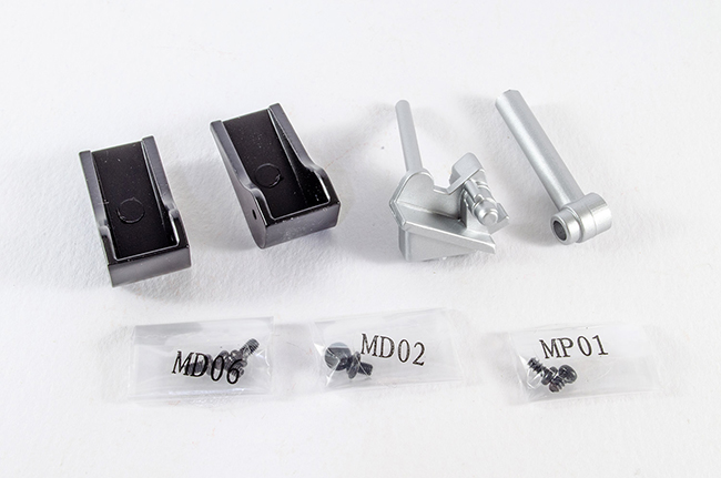 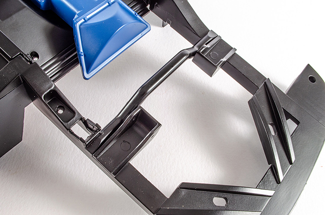 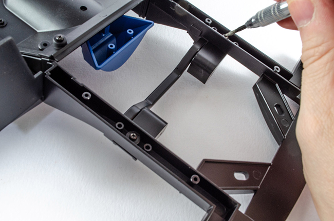 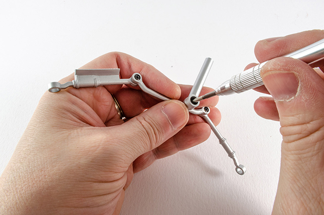 That's it until Pack 5!! For to say this is looking very impressive. 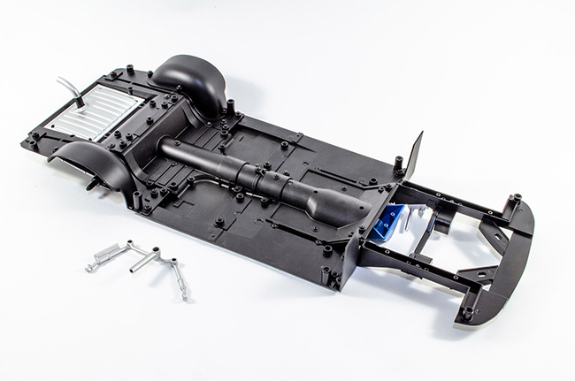 More next time 😘
|
|
|
Rank: Semi-Pro Level 2 Groups: Registered
Joined: 11/01/2017 Posts: 89 Points: 259 Location: Lancashire, UK
|
Pack 5 landed on the doormat late last week, so spent some time on this one. Please excuse some of the interior photos as the velvety interior is quite hard to photo on a white background without highlighting dust etc. The finish itself looks excellent, so I hope I've done it some justice here. STAGE 31: STABILIZER BAR AND LOWER SUSPENSION ARMS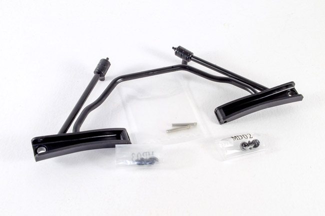 This pack is very simple and just adds the stabiliser bar and suspension arms in a single piece. This needs to be able to pivot and flex to is can take the natural suspension of what will be a very heavy model when completed. The stabiliser bar is first screwed into the forward chassis, and then pins used to locate the suspension arms. The pin is serrated and grips the metal of the chassis. I fitted the stabiliser bar first, unlike the instructions said, as this seemed the most natural thing to do. 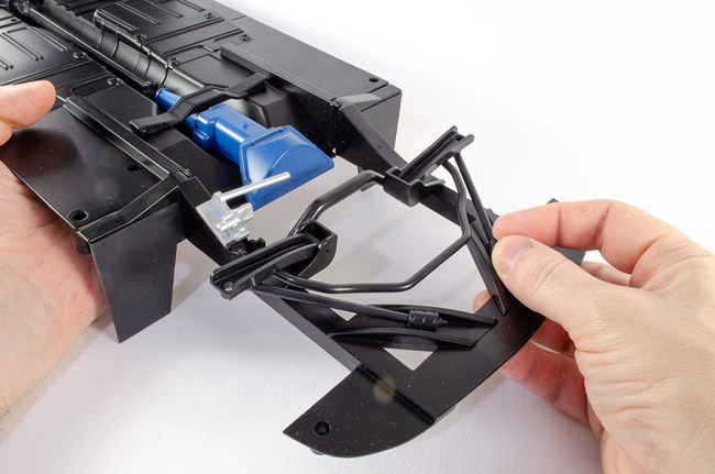 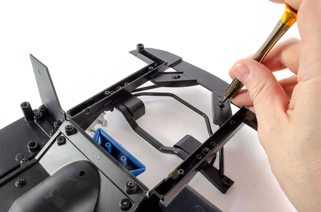 Be careful with the pliers so you don't damage any of the metal paintwork. 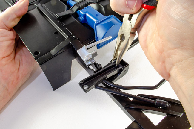 STAGE 32: UPPER SUSPENSION ARMS STAGE 32: UPPER SUSPENSION ARMS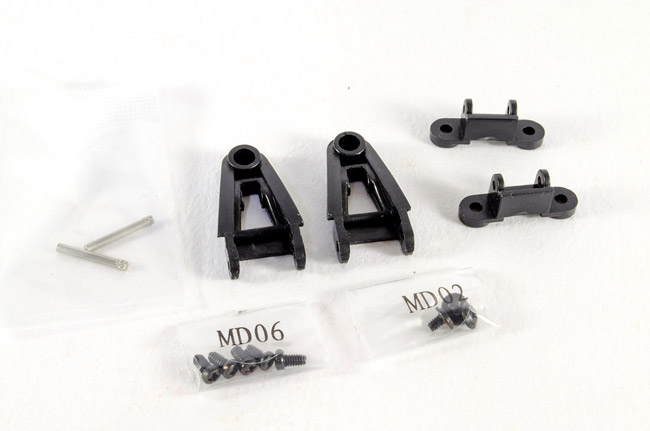 More pins to use here as the suspension arms and supports are assembled. I also found the screws a little tight in the metal, so I first put these into the chassis as far as I could get them, then removed them before using them to fit the suspension arms. 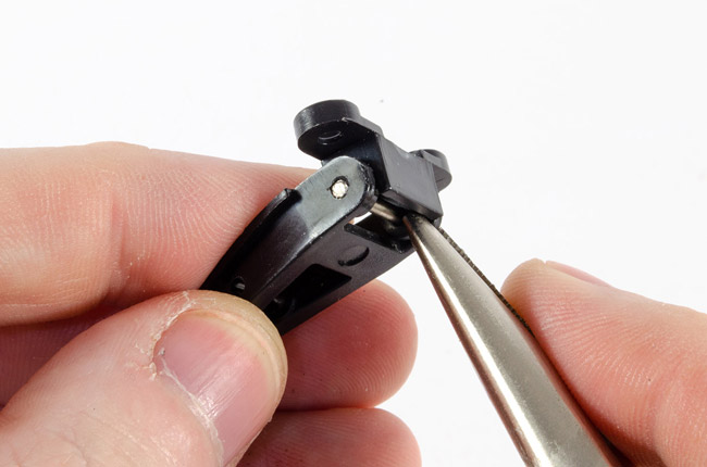 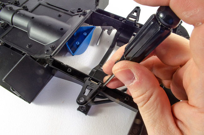 STAGE 33: FRONT INTERIOR FLOOR AND GEAR LEVER STAGE 33: FRONT INTERIOR FLOOR AND GEAR LEVER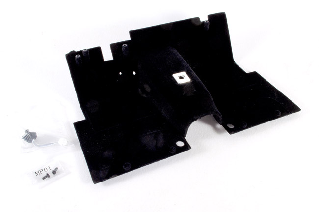 And now for something completely different! Some interior! The interior parts of this model have a black velvet-style finish to them, and you'll need to be careful that you don't mark this as you build. I found a piece of de-tacked masking tape was perfect was removing lint and hairs/dust etc. This pack is simple.....we just screw the gearstick to the interior floor by inserting a screw from underneath. Et voila! 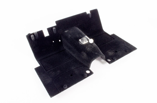 STAGE 34: FRONT SIDE WALLS, PEDALS AND SWITCHES STAGE 34: FRONT SIDE WALLS, PEDALS AND SWITCHES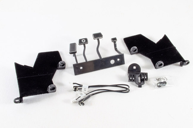 We now see the first of the electronic parts in the form of two microswitches for the accelerator and brake pedals. First though, we fit the front side walls, being careful not to damage that velvet interior finish on them. 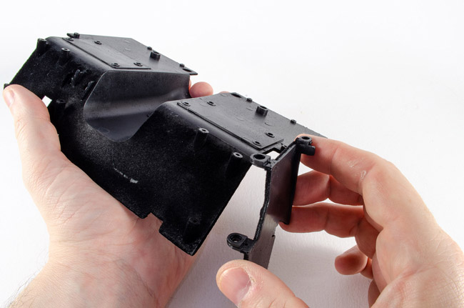 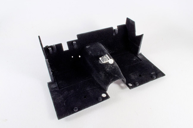 The switches are now located to the switch holder, observing the correct position for each 01, 02. 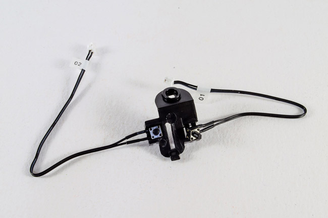 The switch holder is then clicked to the rear of the interior and screwed into place. 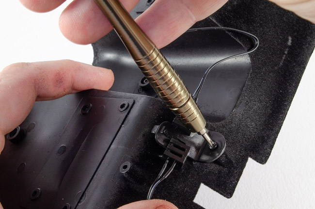 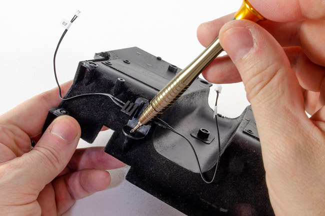 The pedals are now fitted. I had to make sure the pedal plungers went through the holes in the interior and could make contact with the switches. One of these was a little sticky, so repeated operation freed it up so it worked perfectly. 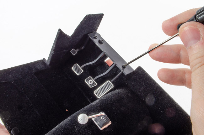 STAGE 35: DASHBOARD AND FUSE COVER STAGE 35: DASHBOARD AND FUSE COVER Another dead simple one. The dashboard and fuse cover are now put together. a single screw from the reverse of the dashboard is driven fully home. 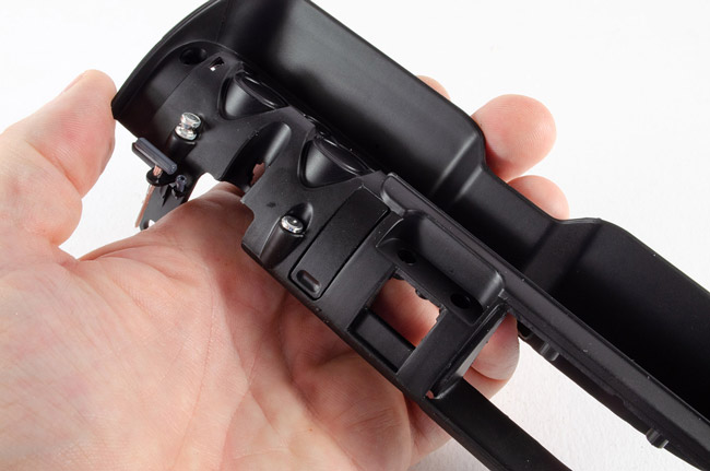 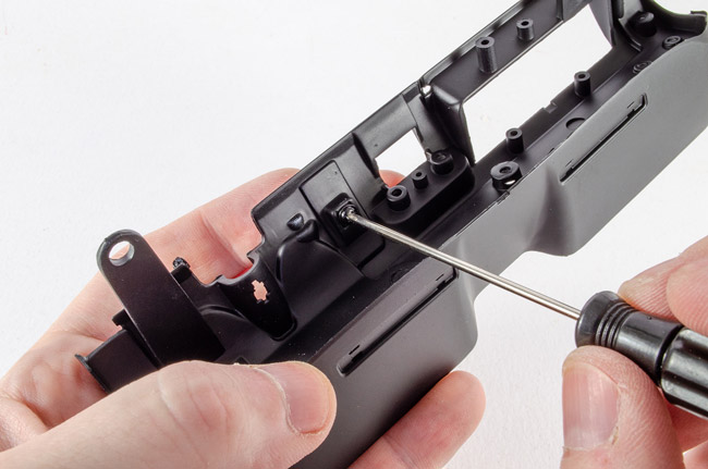 STAGE 36: DASHBOARD TRIM, DIALS AND SHELBY BADGE STAGE 36: DASHBOARD TRIM, DIALS AND SHELBY BADGE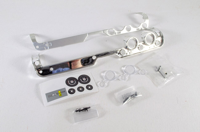 We can now pretty-up the dashboard area. The first thing to do is apply the self-adhesive stickers for the dials. These are clearly identified for location. these are then peeled from the sheet and applied with some tweezers so I get the correct orientation. 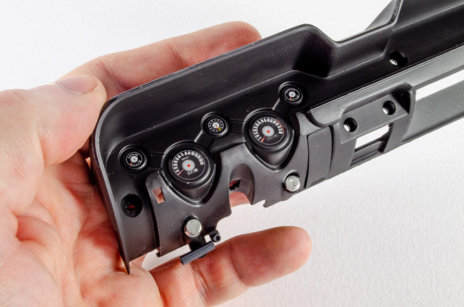 The glass dial covers are then clicked into position on the rear of the dashboard trim. The cloth that came with the kit is then used to remove any fingerprints before the trim is sat in position. 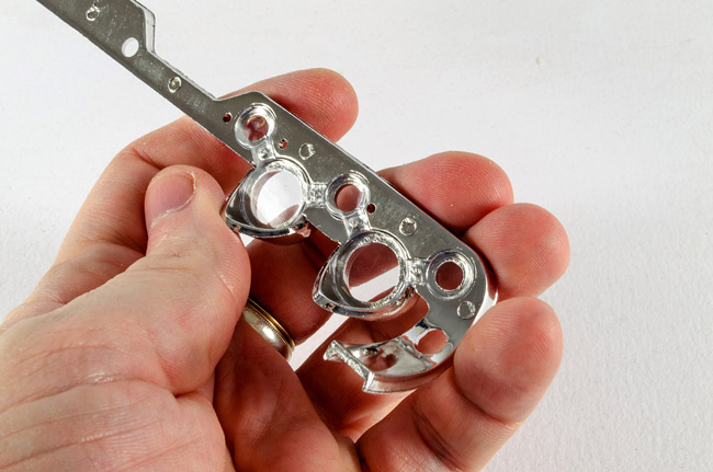 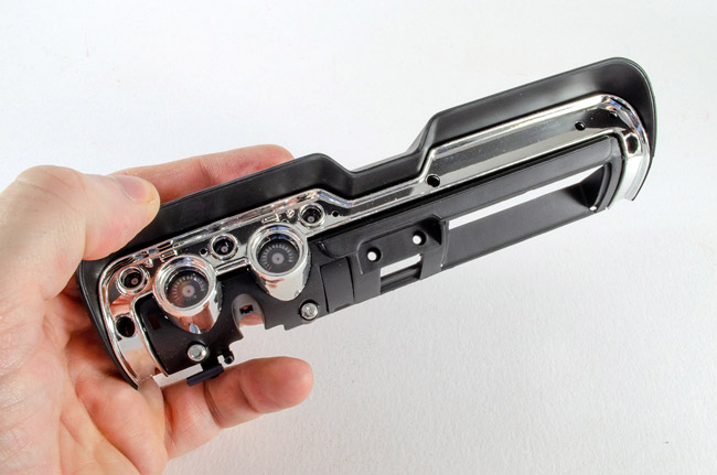 The dashboard strip with its satin finish is now sat over the chrome trim and screwed into position from behind, locking the metallic parts in place.  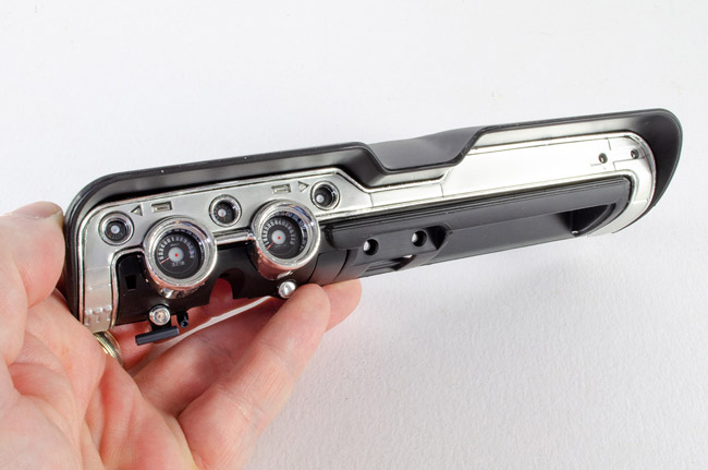 The Shelby badge now has its sticker applied and is screwed to the dash from behind. 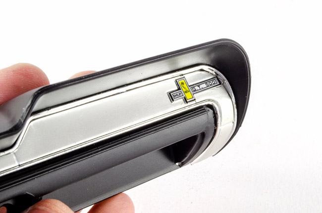 STAGE 37: CENTRAL DIALS, CAR RADIO AND GLOVE COMPARTMENT STAGE 37: CENTRAL DIALS, CAR RADIO AND GLOVE COMPARTMENT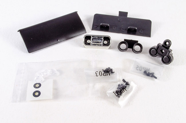 Great to see more interior parts so we can work on the dash. I have to say it's looking pretty darn nice. First up, it's the radio that we need to fit....from the days when you did have to actually tune them in! 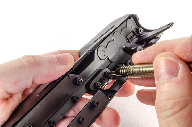 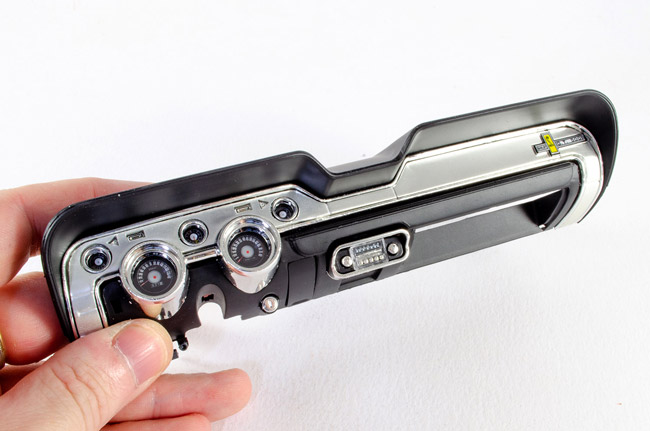 The central dials are now assembled. Firstly, the stickers are added as before, and the dial glass located. I needed to trim a little clear plastic to make this sit flush, and then the frames could be added. The unit was then screwed into position under the radio. 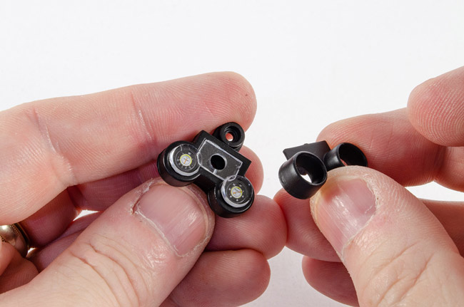 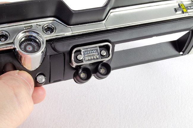 Two parts are supplied for the glove box. The interior is screwed into position and then the door is clicked into place from the front. This will open/close. 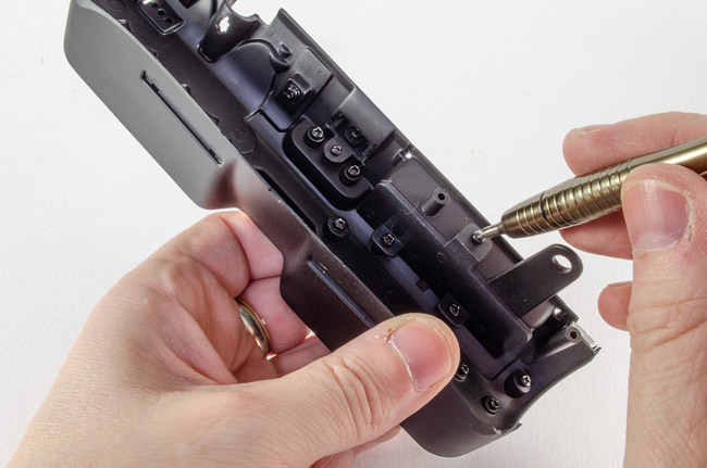 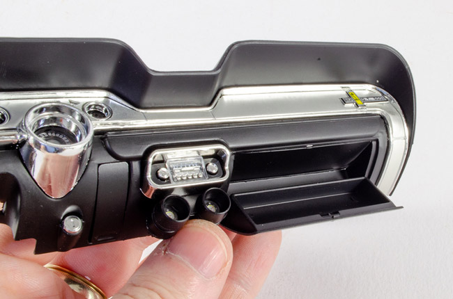 Very excited to see the dash unit could now be fitted to the interior. Two screws holds these large units permanently in position. 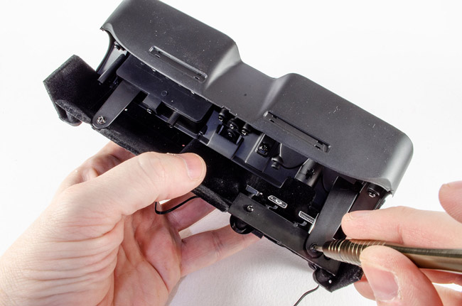 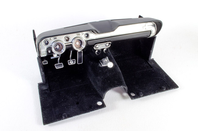 STAGE 38: REAR FLOOR AND FRONT SEAT BELTS STAGE 38: REAR FLOOR AND FRONT SEAT BELTS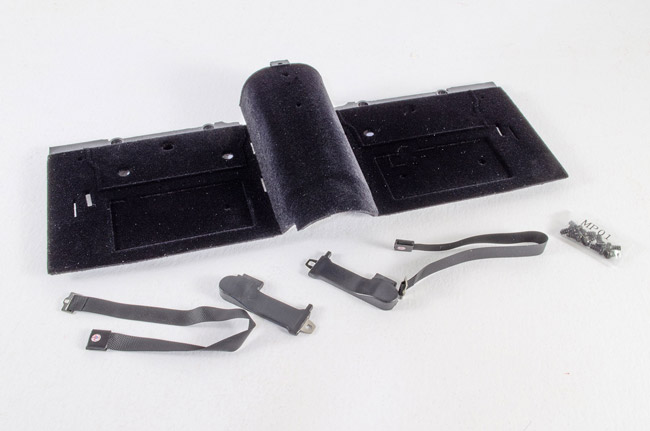 More care is needed here as we have another velvet finish part in the shape of the rear floor. Before we do anything else, the seatbelt anchors are clicked into place in the slots on the floor section. These are quite a tight fit and I needed to remove fingerprints with some de-tacked masking tape on the black surface, when done. 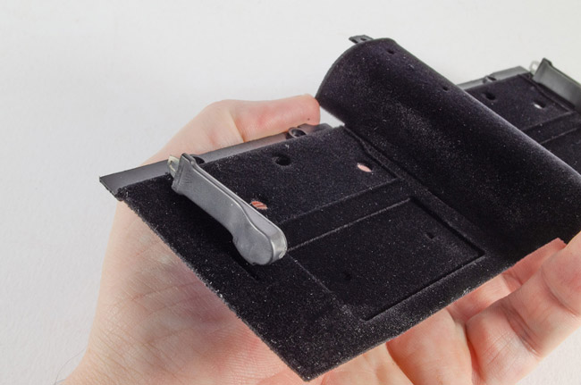 The rear floor is now screwed to the interior section and a central pin used to lock the 'tunnel' together. 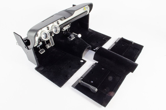 The seatbelts are slotted into position as shown, making sure that the Cobra badge is facing upwards on the clasp. 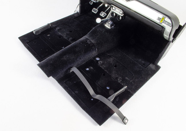 Flip the model over and located the belt to the pips as shown. I needed to use. small spot of CA to make these stay in position. 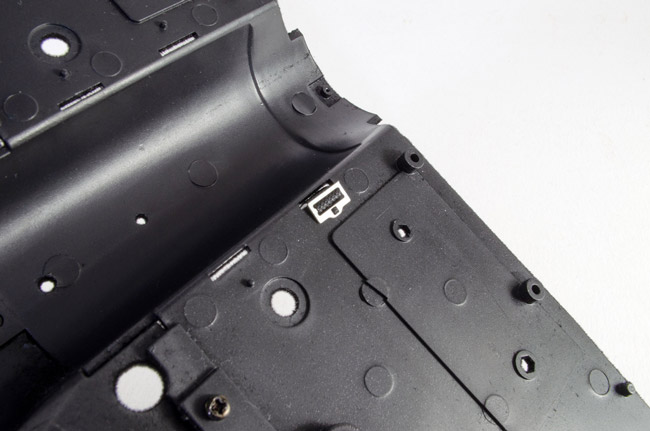 AND AND.....we now have this! 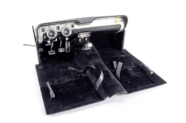 Looking forward to Pack 6!
|
|
|
Rank: Semi-Pro Level 2 Groups: Registered
Joined: 11/01/2017 Posts: 89 Points: 259 Location: Lancashire, UK
|
STAGE 39: INTERIOR DETAILS
Front and Rear Floor Mats and Fire Extinguisher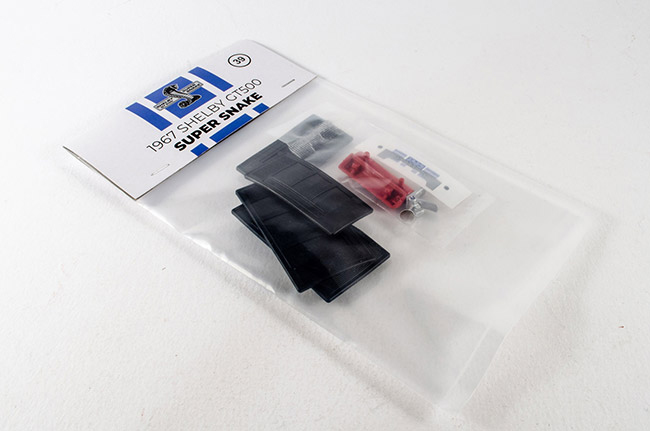 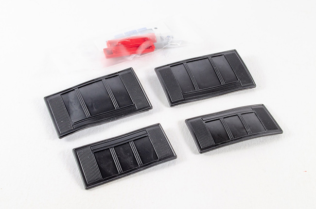 With this new pack, Agora is sticking with working on the interior, and there's detail work as well as the various panels. This first set of parts contains the rubber floor mats and fire extinguisher. The floor mats just push into the holes in the floor. One thing I did need to do was to remove a little of the fibre from the holes, as it was stopping the mat pins pushing fully home. A scalpel was used to clear the holes and the mats pushed firmly in, clicking as they locked into position. 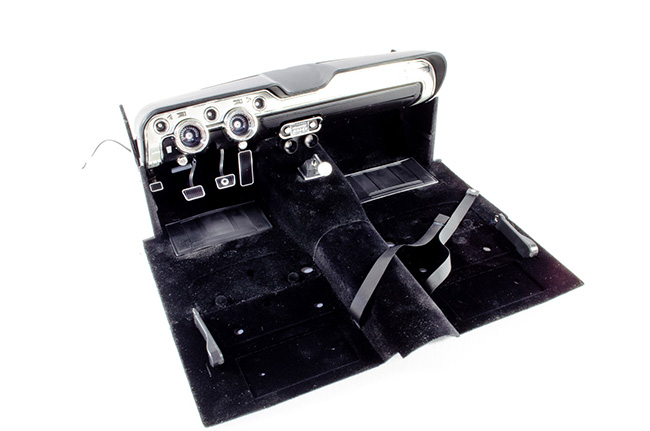 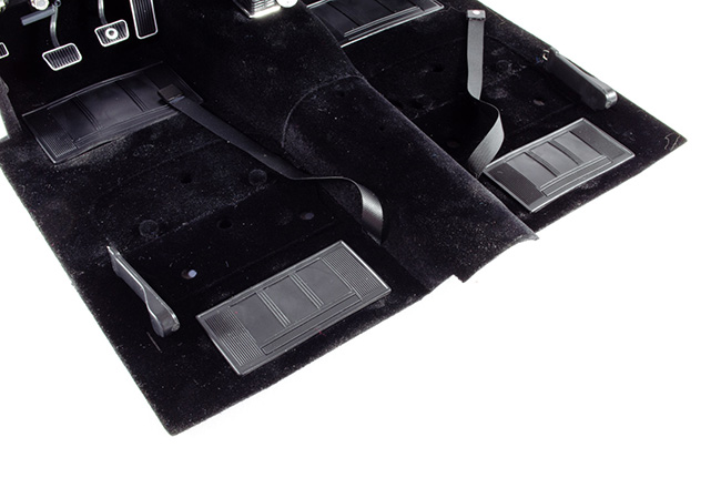 Remember those seats? Those are now fitted to the interior. Note the 'R' and 'L' on the underside and fit them in the appropriate place as shown on the instructions. Two screws hold each in position. 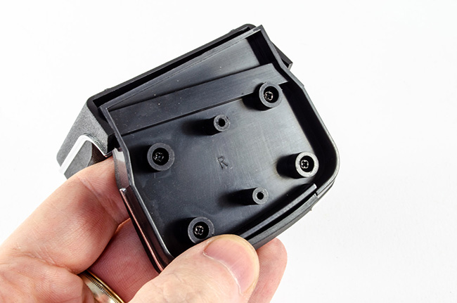 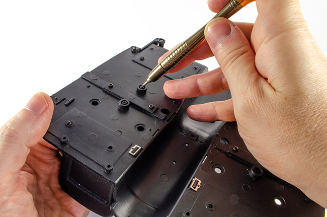 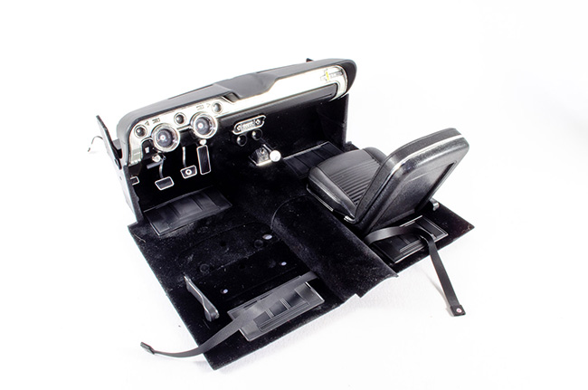 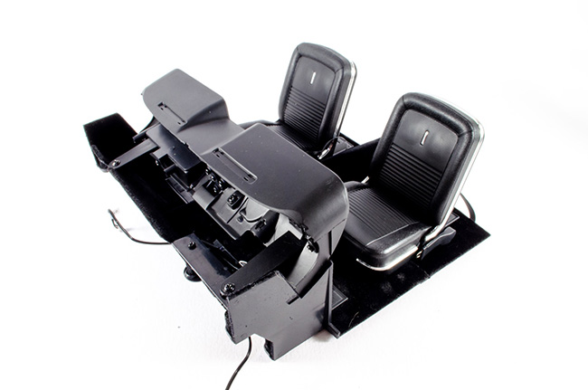 The fire extinguisher is now assembled. The handle is pushed into the lower half as shown here, and then the upper half locks everything into position. A sticker is then carefully applied and the finished extinguisher plugged into place between both seats. 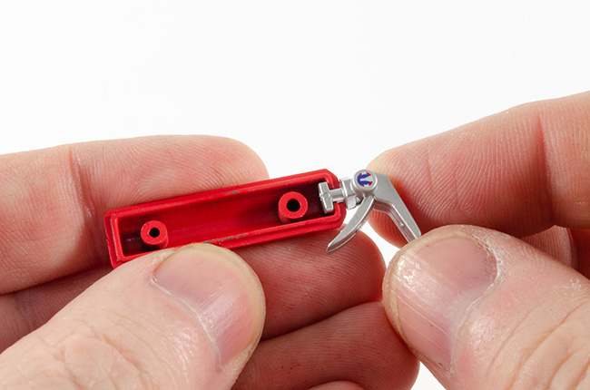 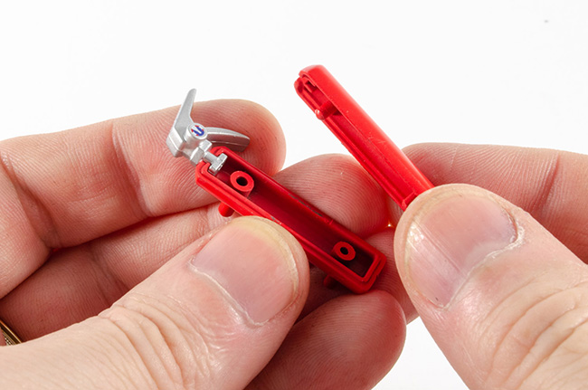 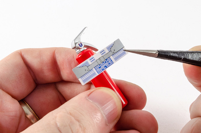 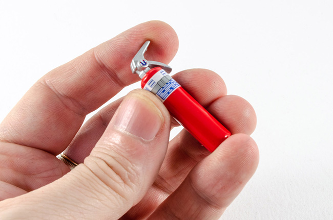 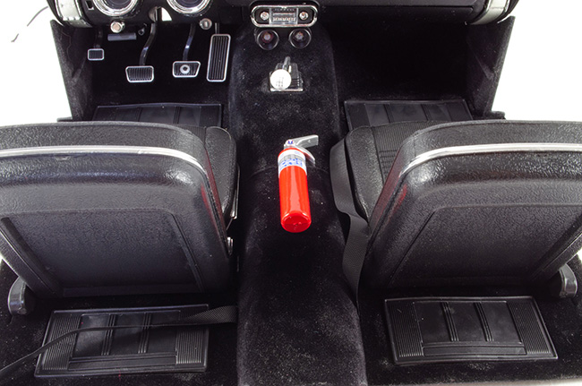 Looking very, very cool! STAGE 40: REAR SEAT SUPPORT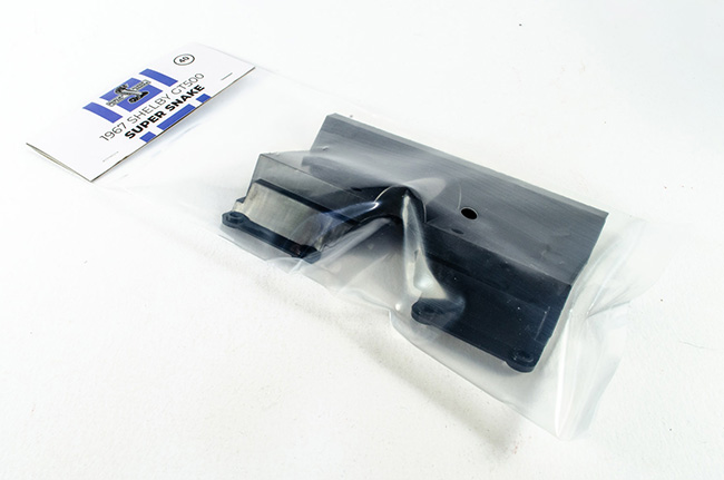 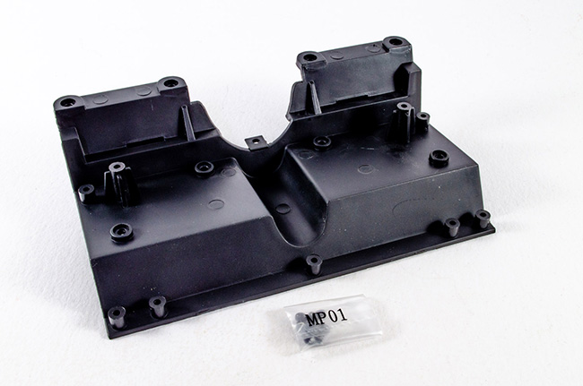 From here, the interior starts to take on a real life and shape of its own. There's only one part in this pack, and this is screwed into position with four screws. You also have to make sure that the tab in the tunnel area is clicked firmly into position as it was with an earlier interior stage. 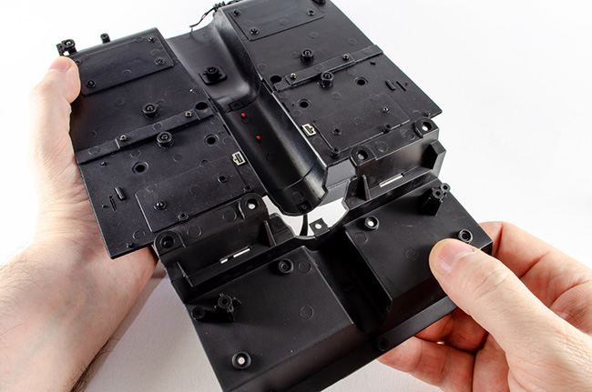 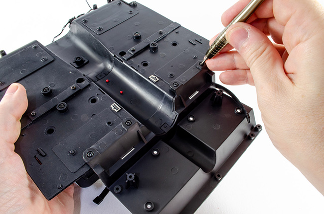 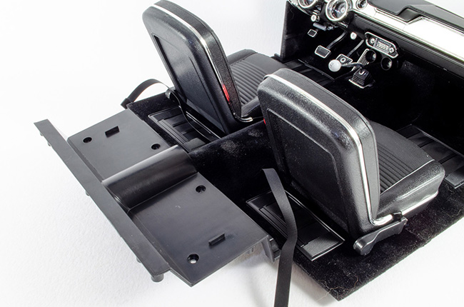 STAGE 41: INTERIOR REAR PLATFORM STAGE 41: INTERIOR REAR PLATFORM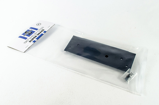 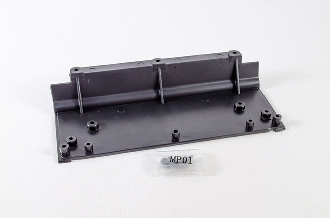 Another pack with just a single part, and this extends the interior even further back. Just three screws hold this in position. 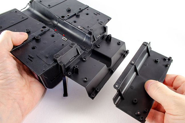 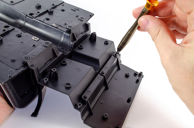 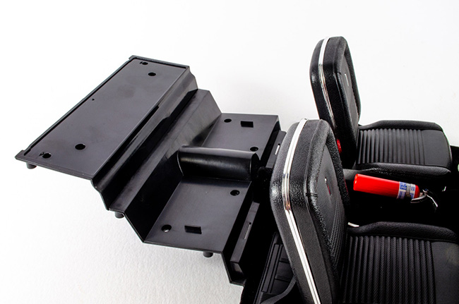 STAGE 42: LEFT REAR INTERIOR PANEL, STAGE 42: LEFT REAR INTERIOR PANEL,
Interior panel, Decorative Accessory and Rear Seat Release Lever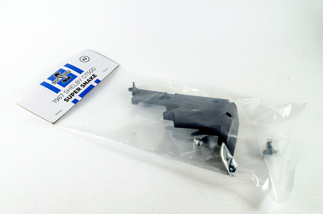 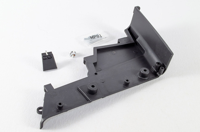 I'm actually very pleased that the side panels are now being fitted as it gives some rigidity to the interior. A 'decorative accessory 🤣' and rear seat release lever are screwed into position on the left interior panel. 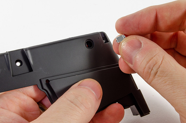 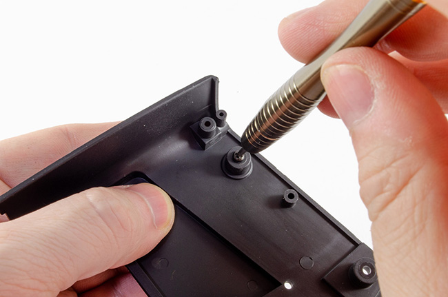  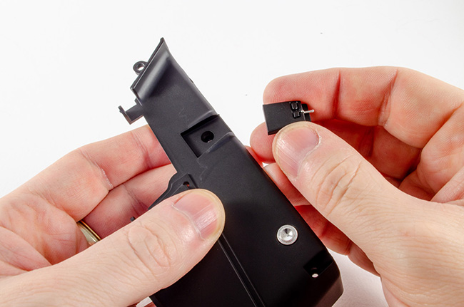 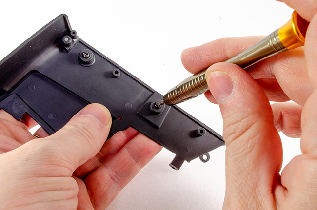 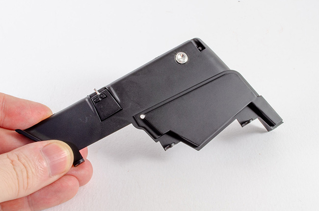 The panel is now screwed into position on the left hand side of the interior. Note that there is a pin locating position on the underside too, which keeps that connection rigid. 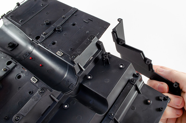 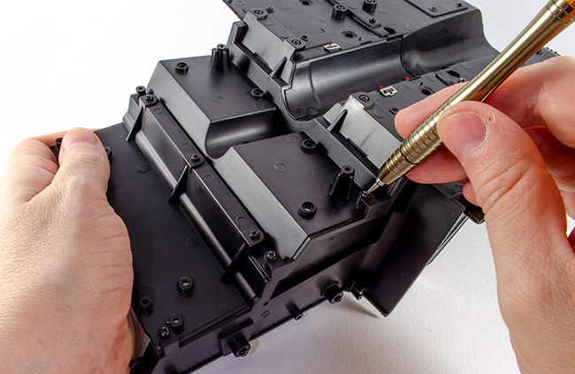 STAGE 43: LEFT REAR UPPER INTERIOR PANEL AND VENTILATION GRILLE STAGE 43: LEFT REAR UPPER INTERIOR PANEL AND VENTILATION GRILLE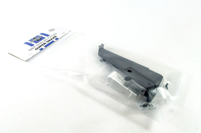 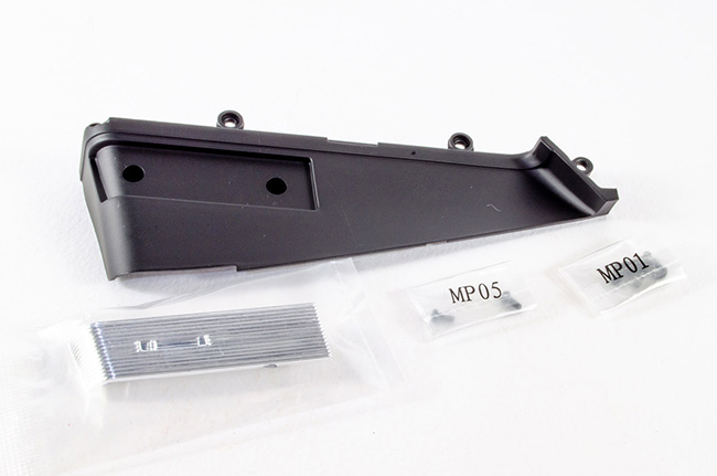 More work on the left hand side now with the upper left interior panel. The ventilation grille is pushed into position and then screwed from the rear. I needed to remove a little plastic flash from the edges of this, which neatened the whole part up. 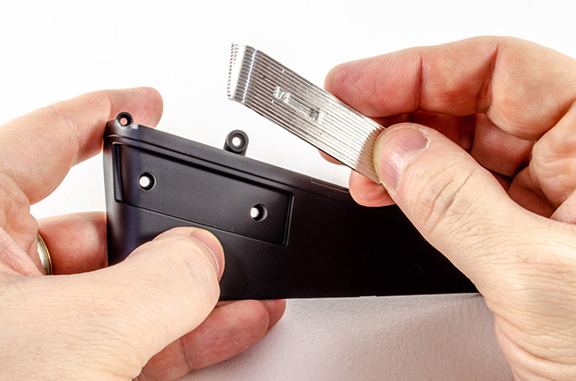 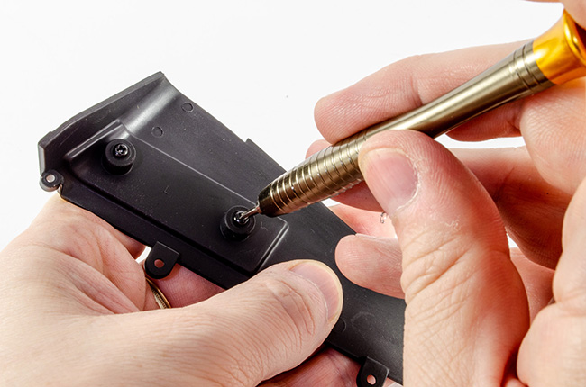 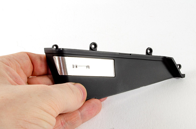 This panel is now fitted above the previous one with just two screws. This will be made far more rigid very shortly. 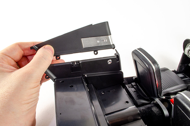 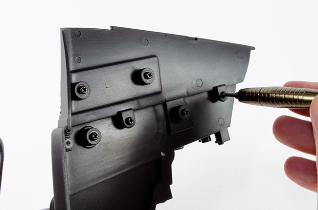 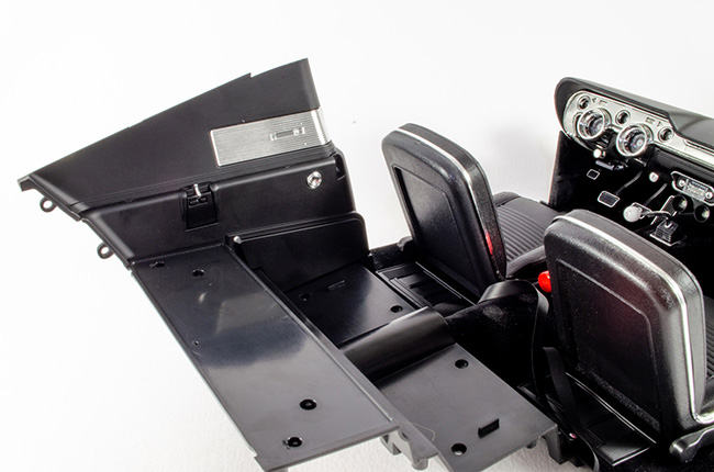 STAGE 44: INTERIOR TRUNK PARTITION PANEL STAGE 44: INTERIOR TRUNK PARTITION PANEL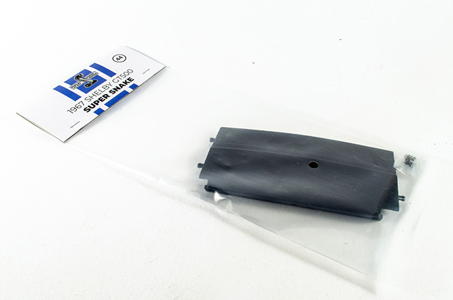 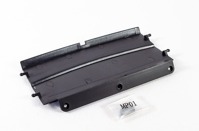 This single part is pretty obvious. It's the interior truck partition panel, and is held to the interior by three screws on the underside. It also secures to the upper left panel with a plug pin fit. I found it easier to push those in first and THEN fit the screws. 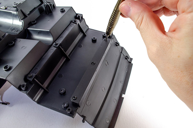 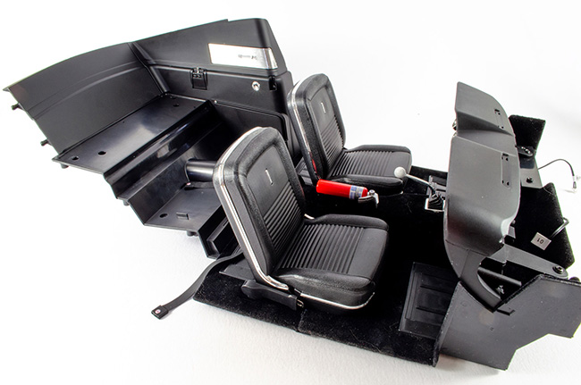 STAGE 45: REAR SEAT FOLDING PANEL AND HINGE STAGE 45: REAR SEAT FOLDING PANEL AND HINGE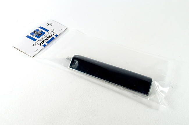 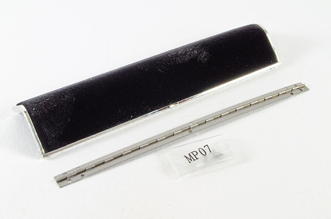 We now see some very tiny screws here, almost like those in a jeweller's box. First, the hinge is located as shown, and then three of those tiny screws are used to secure it to the rear seat folding panel....... 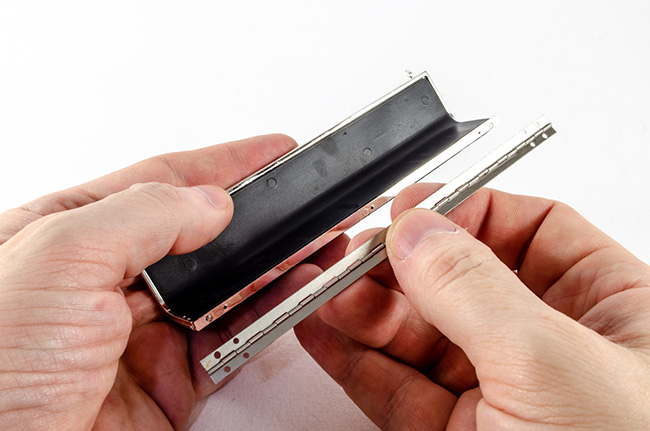 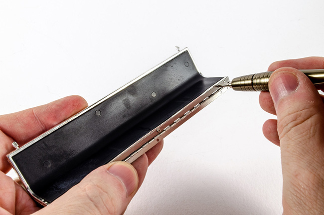 STAGE 46: REAR SEAT BACKREST PANEL STAGE 46: REAR SEAT BACKREST PANEL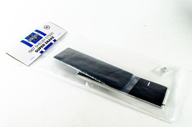 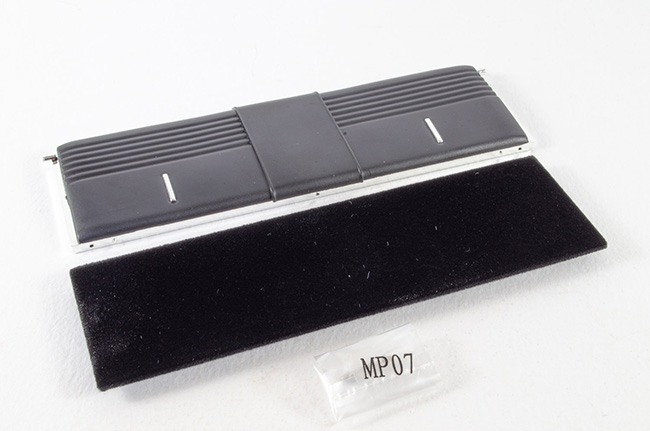 .....then we are onto the next pack of parts! Take the rear seat back, and rear seat back panel, and carefully push them together. 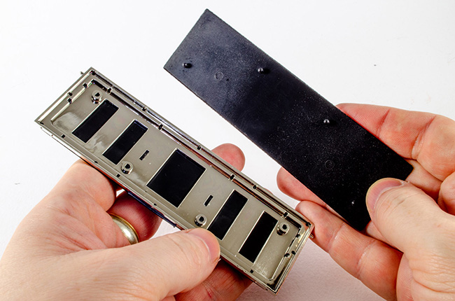 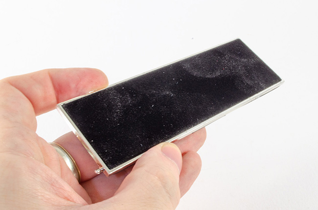 Now screw the other edge of the single to the assembly. 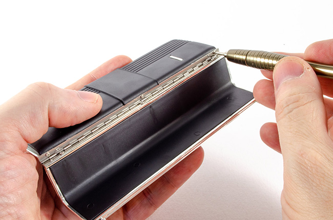 And, er......that's it for another month! Got to say I'm loving this build!!
|
|
|
Rank: Semi-Pro Level 2 Groups: Registered
Joined: 11/01/2017 Posts: 89 Points: 259 Location: Lancashire, UK
|
Are we really already on Pack 7? 😲 Ok, there's some repetition in this with the previous pack, so I'll not repeat lots of photos of the same, but there's still plenty I've had to edit for this update. STAGE 47: RIGHT REAR INTERIOR PANEL: Decorative Accessory and Rear Seat Release Lever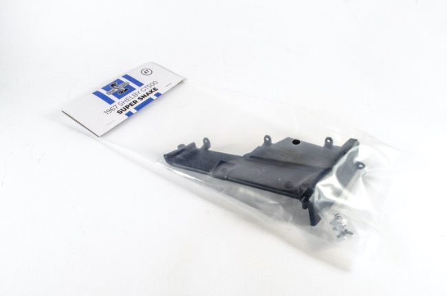 This is simply a reproduction of the left hand rear interior panel. 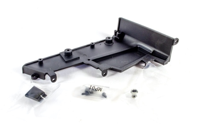 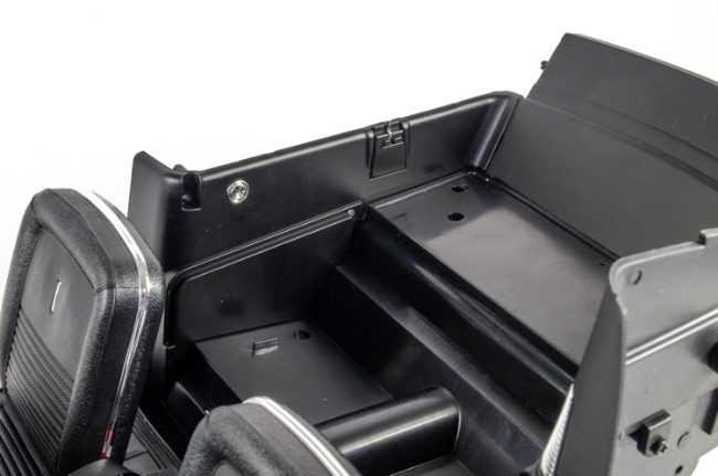 I didn't fasten in the folding seat part at this stage as I didn't want to mark its surface as I progressed. This was fitted right at the very end. STAGE 48: LEFT REAR UPPER INTERIOR PANEL AND VENTILATION GRILLE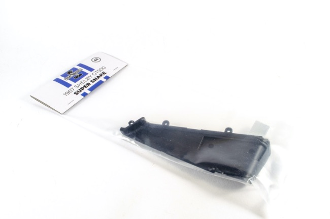 A little more repetition here as left rear upper interior panel mirrors the one we built in the previous pack. 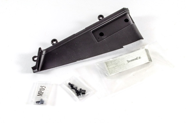 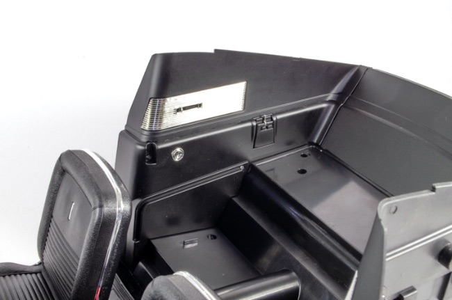 STAGE 49: LOWER DASHBOARD PANEL, ROLL BAR AND SEAT BELTS STAGE 49: LOWER DASHBOARD PANEL, ROLL BAR AND SEAT BELTS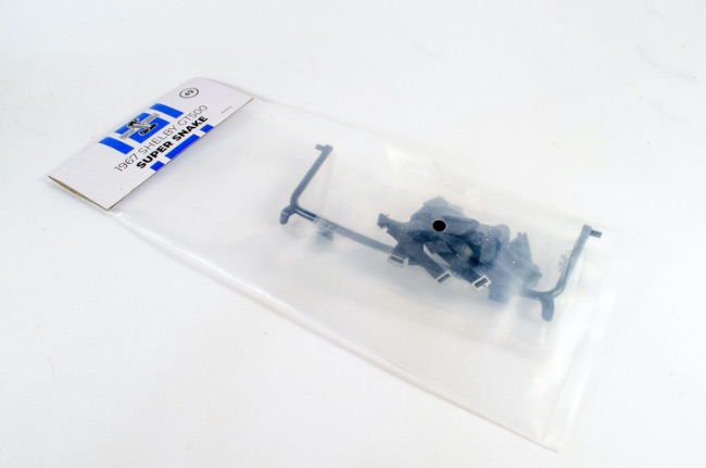 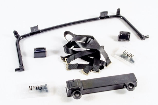 Ok, onto some nice interior detail stuff now. The first thing to do is to install the lower dashboard panel. The instructions say you can unscrew the dashboard to fit this but I didn't feel that was necessary. It was very easy to fit with a screwdriver with a long shank. 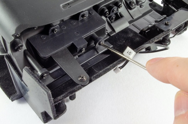 The seatbelts are also very simple. These need to be slotted into the retractor units so that the textured surface of the belt is seen pointing forwards. Once slid into the retractors, the clip is bent over and locks into the unit. That's quite clever. No glue needed. The units are then screwed to the roll bar and the whole unit fastened to the car interior. 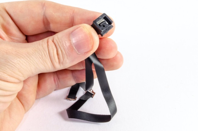 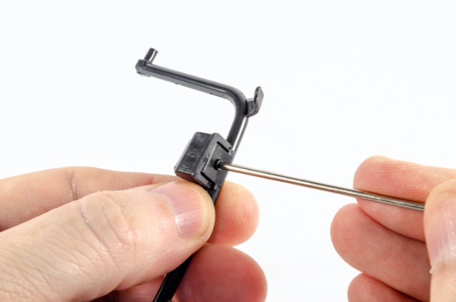 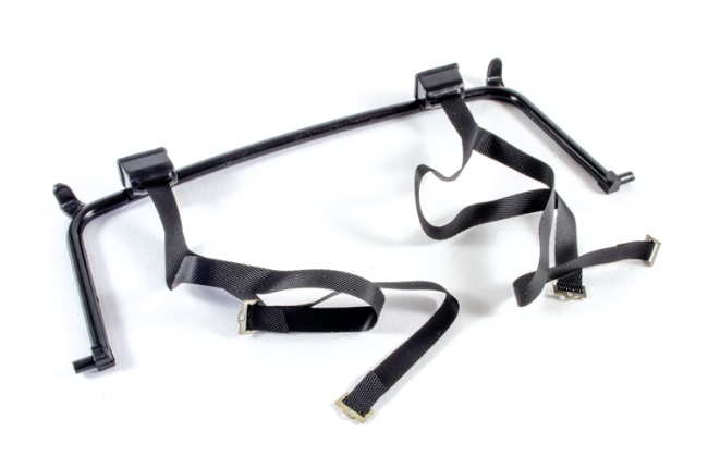 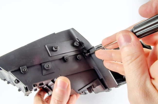 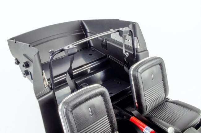 STAGE 50: REAR SEAT AND SEAT BELTS STAGE 50: REAR SEAT AND SEAT BELTS 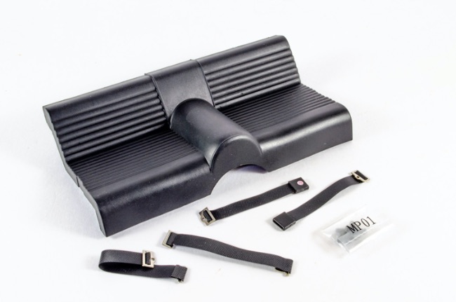 Now we can build and install the rear seat. The unit is actually moulded as a single piece, but the seatbelts must be fitted, making sure that the textured surface faces upwards. For a little insurance, I used a spot of CA on the underside where they connect to the moulded pin. 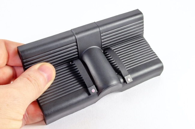 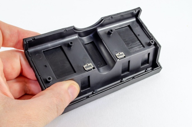 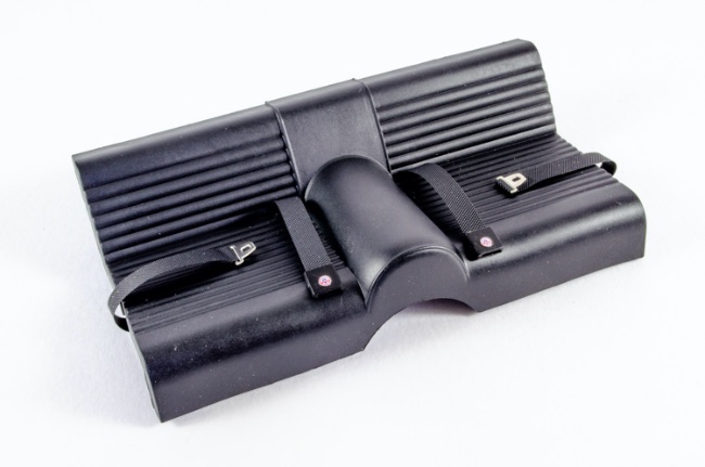 The seat is now fitted to the interior with four screws.  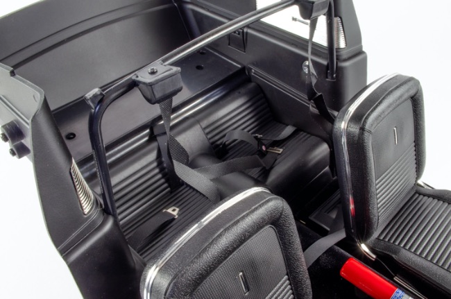 STAGE 51: REAR PLATFORM AND SEAT-BACK LOCKS STAGE 51: REAR PLATFORM AND SEAT-BACK LOCKS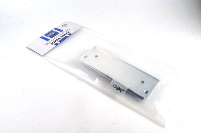 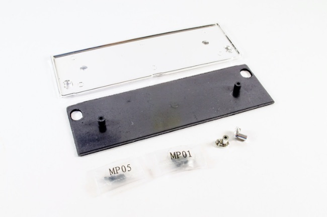 The rear platform consists of two main parts where simply push together, making sure the holes in two top corners are aligned. This unit is then screwed into the interior and the seat locks pushed through the holes and also secured with screws from underneath. 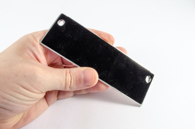 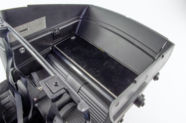 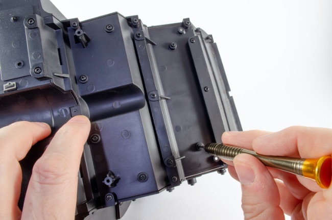 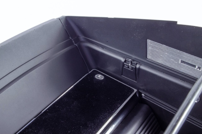 Got to say that I'm finding this interior real impressive at this stage! 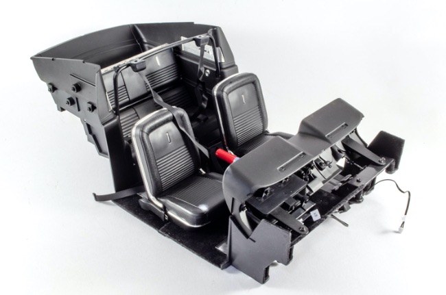 STAGE 52: LEFT FRONT WHEEL: Tire, Rim, Brake disc, Wheel hub, Brake Caliper and Hubcap STAGE 52: LEFT FRONT WHEEL: Tire, Rim, Brake disc, Wheel hub, Brake Caliper and Hubcap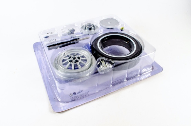 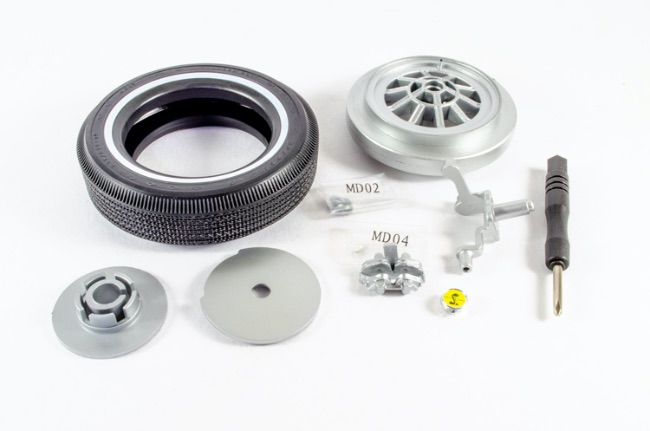 Now I can look at something else other than the interior, which I suspect is almost complete apart from steering wheel etc. Time for a different wheel. To fit the rim to the tyre, you really do need to soften the rubber. You'll not fit this unless you have superhuman strength, without leaving the tyre in freshly boiled water for 5 mins. After that, it goes together real quickly. 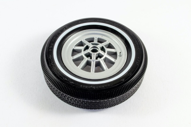 Now the brake disc and calliper can be assembled. 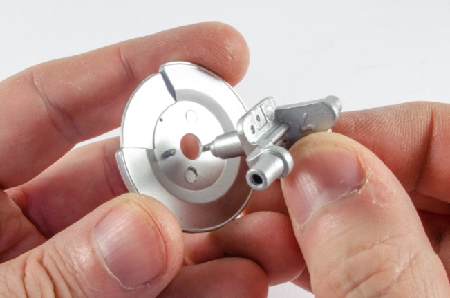 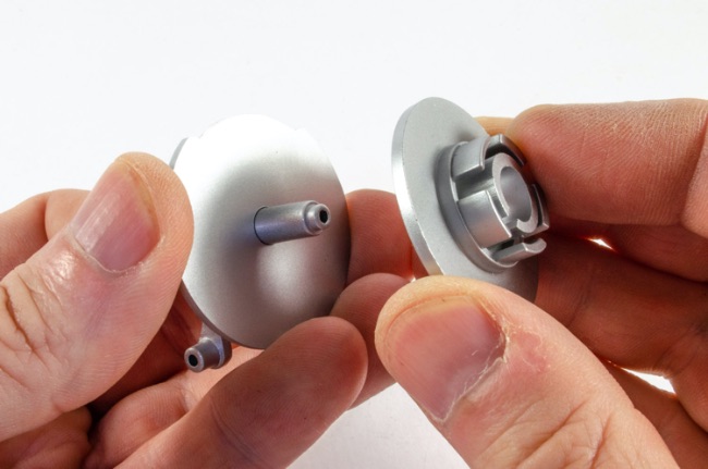 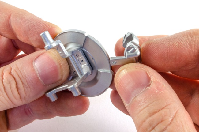 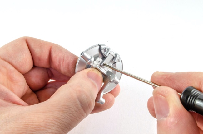 Note the slot and peg on these parts and put them together. A quick spin of the brake disc unit will soon locate properly to the rim. A single screw is then used to fasten them together before the Shelby logo badge is pushed into place over the screw hole. 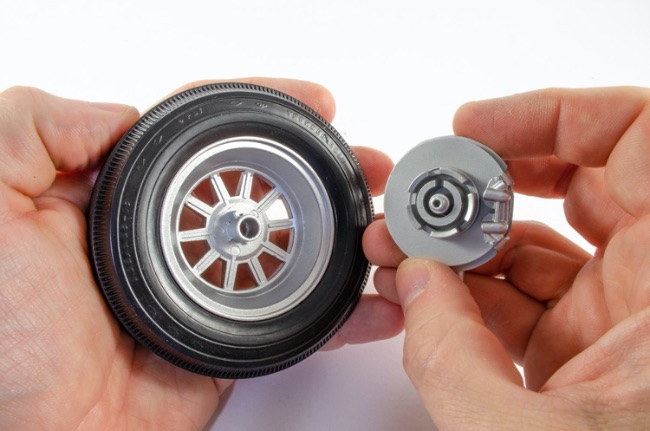 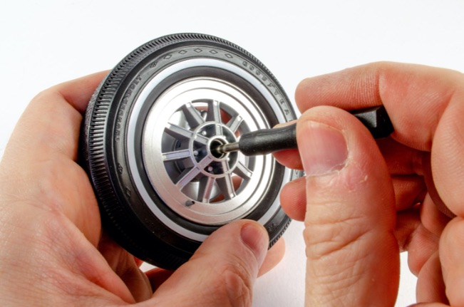 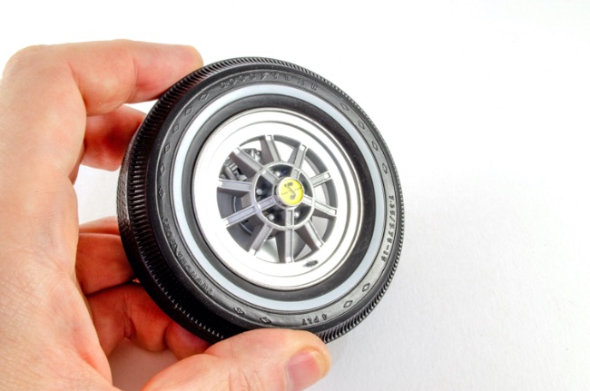 STAGE 53: RIGHT FRONT TIRE AND RIM STAGE 53: RIGHT FRONT TIRE AND RIM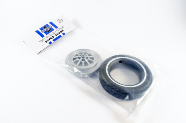 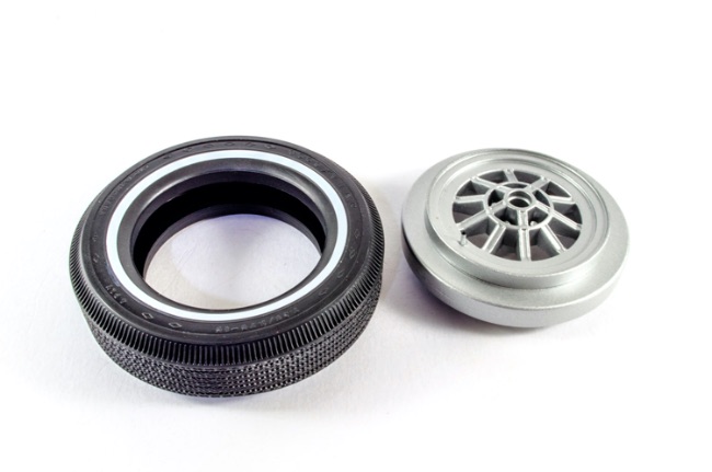 Again, freshly boiled water is used to soften the rubber before the rim is fitted. 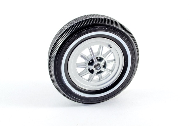 STAGE 54: MUFFLER AND EXHAUST PIPES STAGE 54: MUFFLER AND EXHAUST PIPES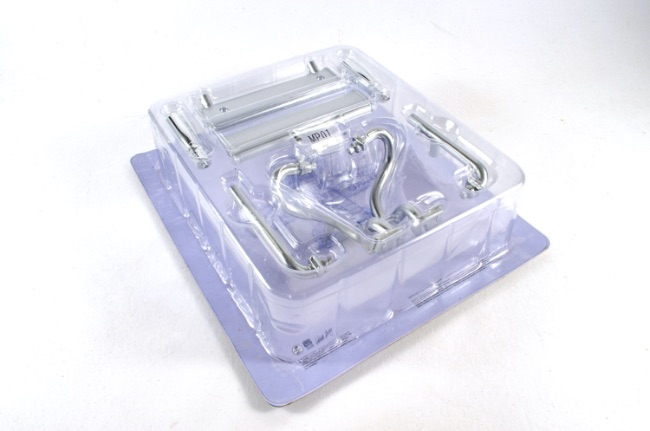 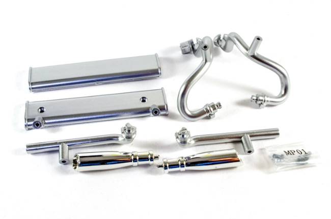 A slight diversion with this pack as I build the muffler. Note that I don't fully screw the body of this together as the various pipes need to be interred and locked into the ends of it. When in position, the body is tightened up and the chrome exhaust tips fitted with. spot of CA. 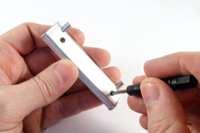 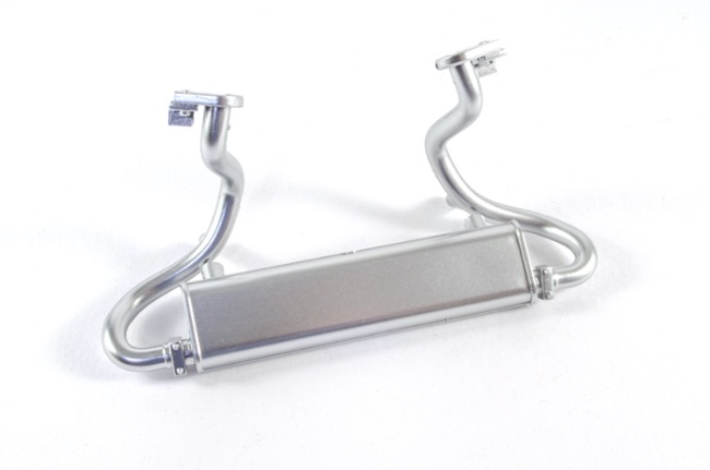 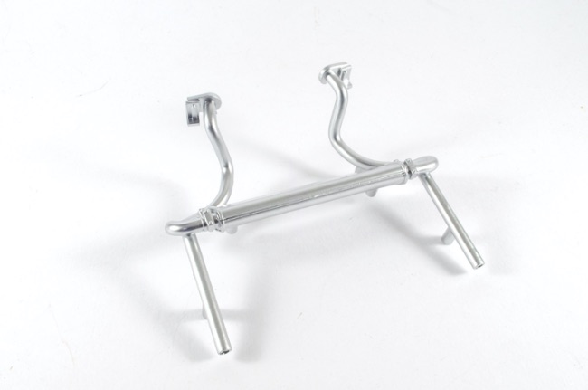 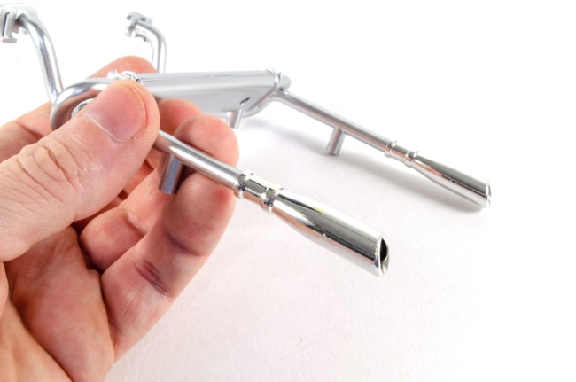 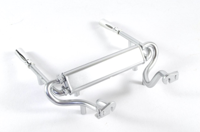 STAGE 55: RIGHT FRONT WHEEL PARTS: Brake disc, Wheel hub, Brake Caliper and Hubcap STAGE 55: RIGHT FRONT WHEEL PARTS: Brake disc, Wheel hub, Brake Caliper and Hubcap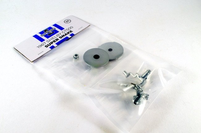 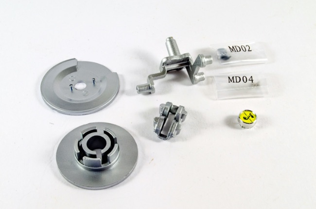 You get the idea with this. We are repeating what we did with the left wheel. Just make sure you don't get these mixed up. The right front wheel is now fitted to the tie rod. I found I needed to drill the hole on the calliper as the screw would barely go in there. 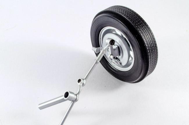 The left wheel is now fitted and again, I drilled out the wheel hole to allow the screw to properly fit. 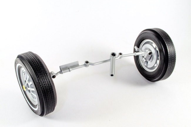 The completed unit is fastened to the chassis so that the ratchet on the tie sits within the mechanism that was fitted when the chassis was built. This makes a ratchet sound when turning the wheels. 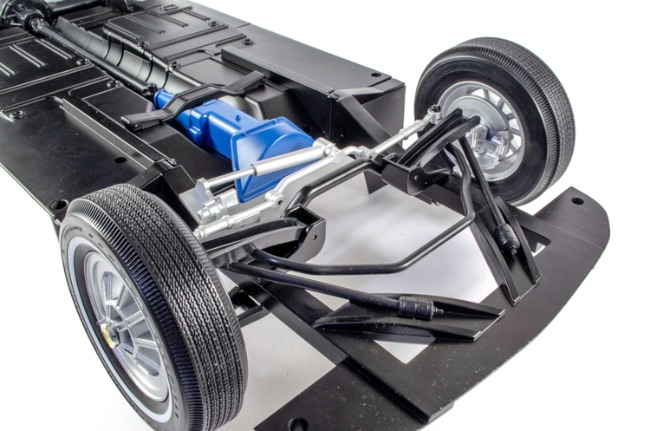 More next time!
|
|
|
Rank: Semi-Pro Level 2 Groups: Registered
Joined: 11/01/2017 Posts: 89 Points: 259 Location: Lancashire, UK
|
Pack 8
STAGE 56: SHOCK ABSORBER AND LEFT REAR BRAKE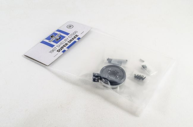 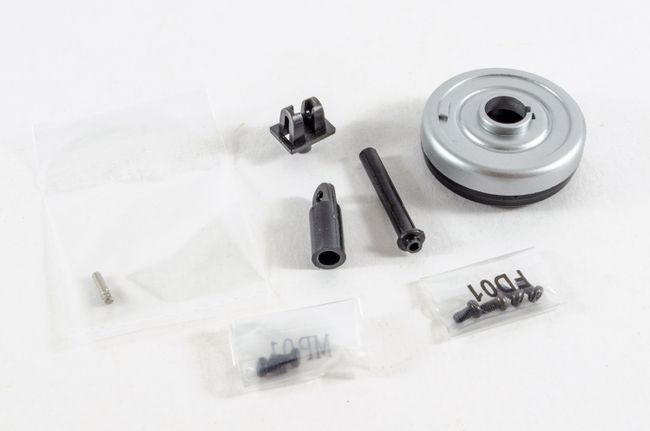 The shock absorber cylinder and mounting plate need to be fitted together. A small steel pin is supplied for this and this is pushed into the assemblies as shown. The serrated end grips the plastic and holds everything together tightly. 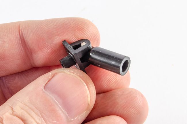 The assembly fits to the left side of the car on the underside as you can see here, and fastened via a screw on the reverse. You also need to remove the shock absorber sprint plate so you can fasten the piston to the underside. This is then replaced, fitting the piston into the cylinder body. The instructions show the left rear brake pushed into position, but as this will just drop off until the wheel is fitted, I kept this to one side. 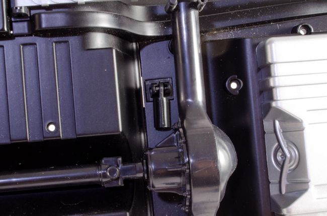 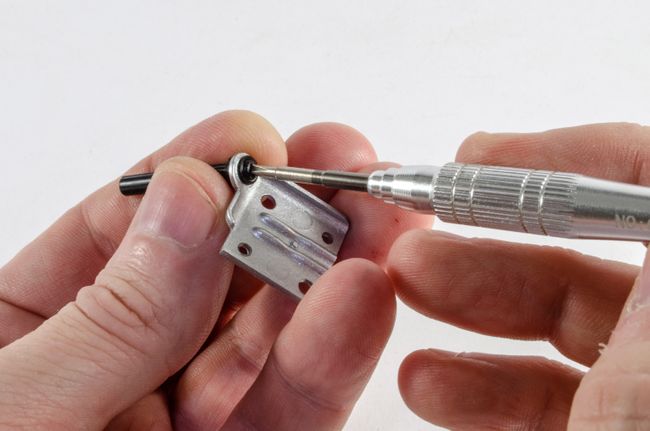 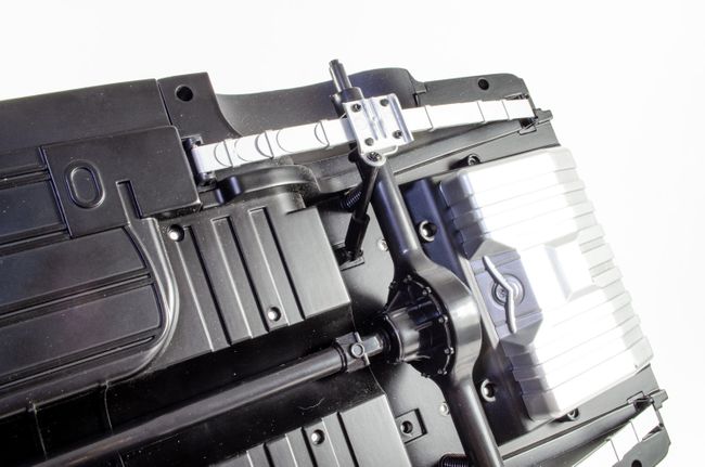 STAGE 57: LEFT REAR WHEEL STAGE 57: LEFT REAR WHEEL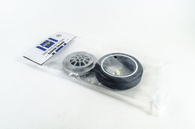 Now, about that wheel! This is assembled in the same way as the previous two, leaving the rubber tyre in hot water for 5 minutes to soften it enough to fit the rim. The brake then slides onto the wheel and signed with the slot. The wheel is then fitted in place with a screw and the Shelby cap used to hide the screw. 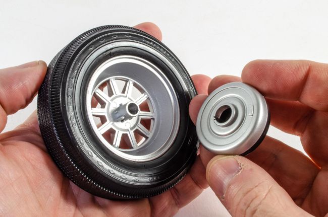 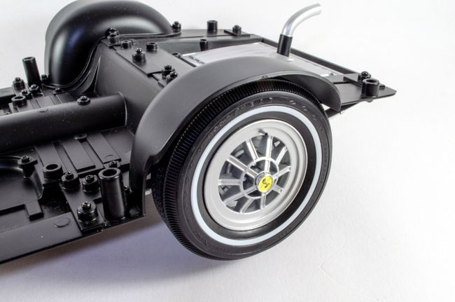 STAGE 58: SHOCK ABSORBER AND REAR RIGHT BRAKE & STAGE 59: RIGHT REAR WHEEL STAGE 58: SHOCK ABSORBER AND REAR RIGHT BRAKE & STAGE 59: RIGHT REAR WHEEL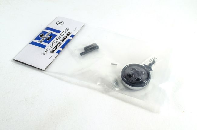 These are simply repeats of the previous stages 56 and 57, but for the right side rear wheel. STAGE 60: EXHAUST SYSTEM ASSEMBLY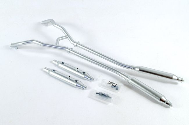 Before you can do anything with this stage, you need to remove this floor pan section. Care is needed not to mix the screws up as there are three different types here, but two of those types are for the channel, so it's pretty easy to sort. An upwards twist helps remove the part. 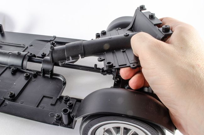 The previous exhaust assembly can now be screwed into position as shown here with the chromed exhausts protruding from the rear. This fastens with 6 screws and you really can't make a mistake here. 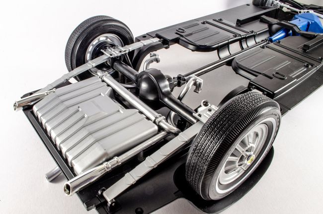 Next, the resonator pipe halves are screwed to the exhaust system, and the completed assembly then fitted to the chassis, followed by replacing the floor pan section. 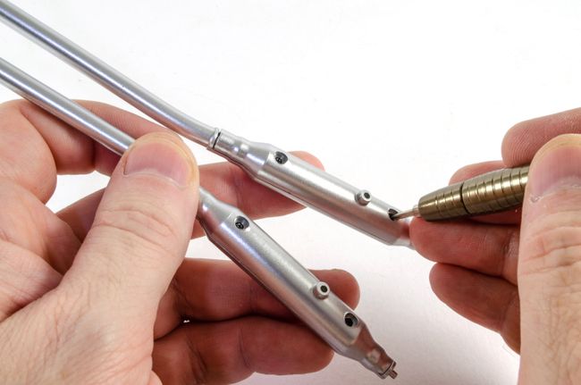 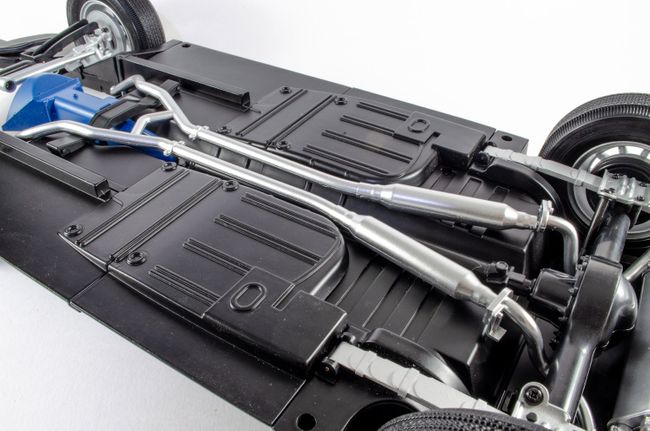 STAGE 61: STEERING COLUMN AND STEERING WHEEL STAGE 61: STEERING COLUMN AND STEERING WHEEL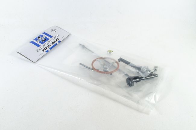 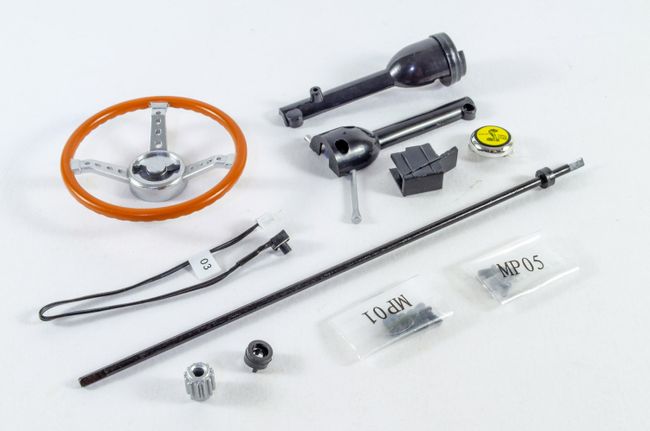 First, the pinion pushes onto the steering column. Both of these parts are metal. 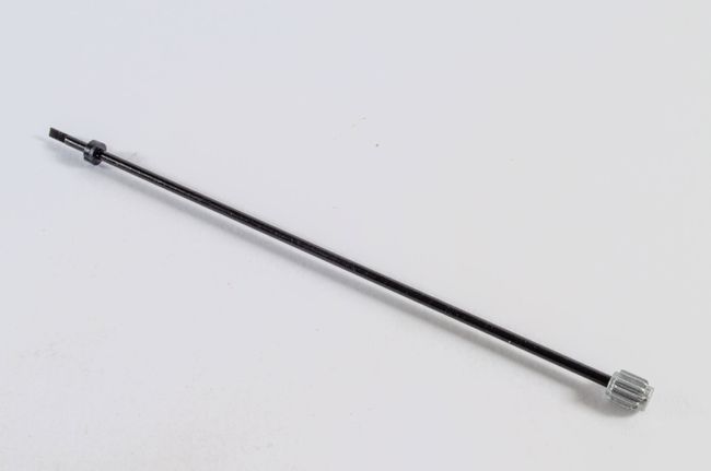 The microswitch is now added. I used a spot of CA on the underside as the subsequent assembly showed this pop out of position. Easy fix. 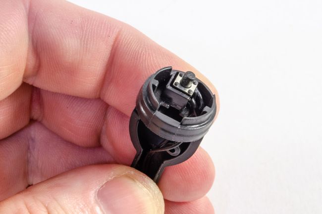 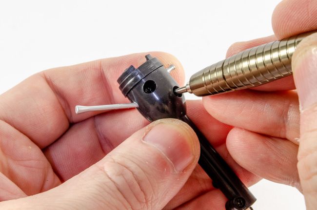 In my case, I had to later repeatedly fit and remove the assembly as it appeared the steering column was a tad overlong. This meant that I couldn't push the pinion down into the chassis far enough without the steering column pushing the wheel away from the housing and microswitch. To fix this, I filed away the bottom of the pinion that wasn't serrated, and also took 1mm off the top of the column where it entered the steering wheel. The whole lot now works great when fitted to the model. 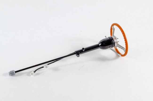 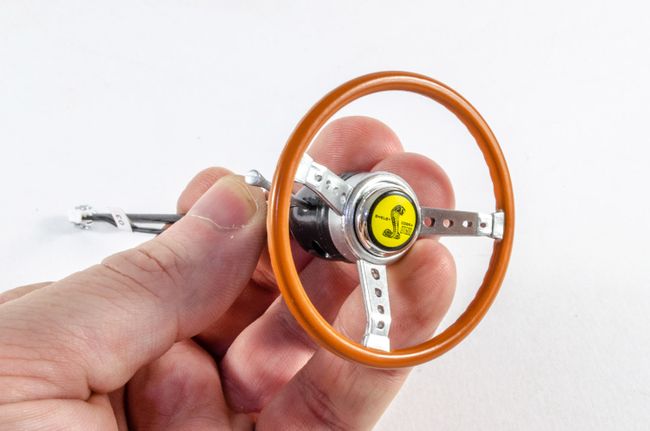 STAGE 62: TRUNK PANEL STAGE 62: TRUNK PANEL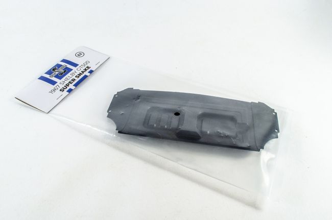 Nothing to see or do here, so move along! STAGE 63: SPARE WHEEL, STEERING WHEEL AND FLOOR ASSEMBLY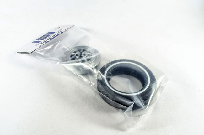 This wheel is assembled as the others and will be the spare that is kept in the boot. 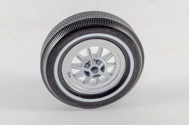 The steering wheel can now be fitted to your model, although I think this is best done when the interior is bolted to the chassis because there's less chance of damaging it, and also more chance of getting everything aligned properly. 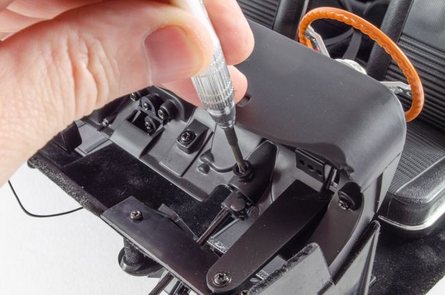 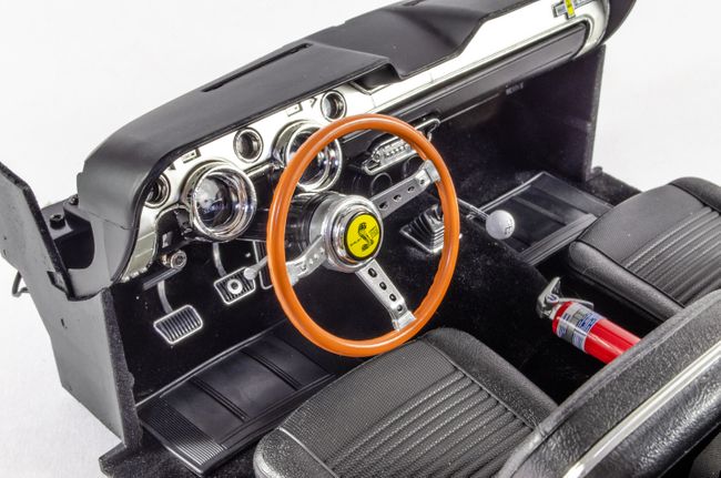 The interior is now fitted to the chassis... 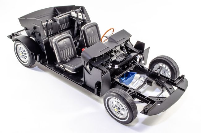 ...and here you see the cap which pushed into place to hold the pinion down onto the rack. 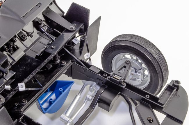 STAGE 64: TRUNK PANELS, JACK, AND FIXING THE SPARE WHEEL STAGE 64: TRUNK PANELS, JACK, AND FIXING THE SPARE WHEEL 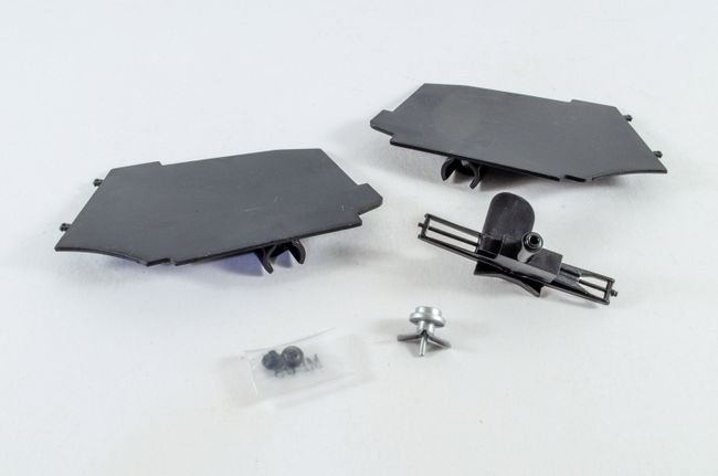 Using the panel we got earlier, the side plates are now fitted to it by clip connections. The assembly is now fitted to the car. 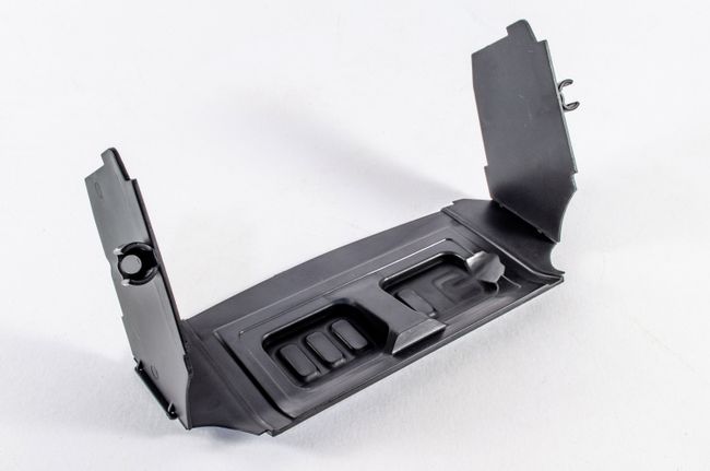 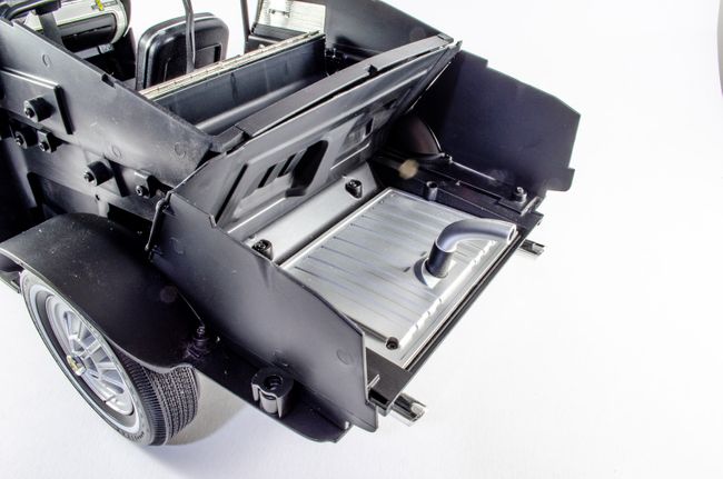 The spare wheel is now made up with the mechanism to lock it into position. 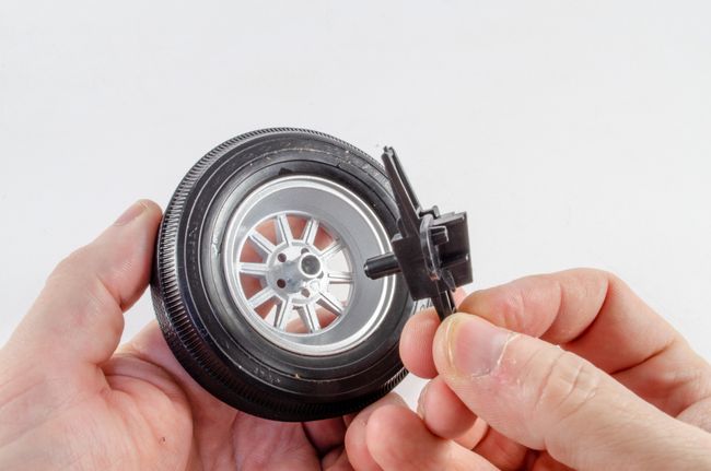 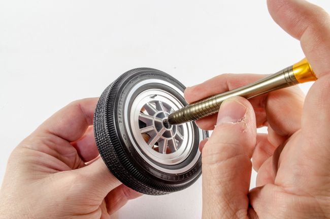 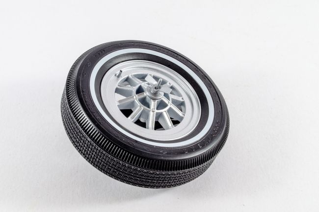 Finally, the wheel is fitted. 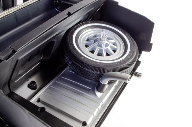 I'll post Pack 9 tomorrow to get myself up to date.
|
|
|
Rank: Semi-Pro Level 2 Groups: Registered
Joined: 11/01/2017 Posts: 89 Points: 259 Location: Lancashire, UK
|
Pack 9
STAGE 65: FIRST PARTS OF THE RADIATOR  This one's quite simple. The grille sits on the radiator and is trapped by he fan bracket which is fastened with a screw from the rear.  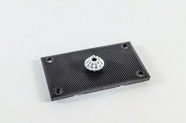 STAGE 66: RADIATOR SHROUD AND FAN BLADE STAGE 66: RADIATOR SHROUD AND FAN BLADE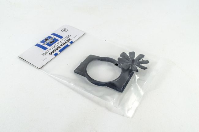 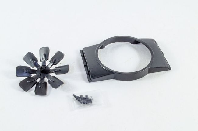 Construction of the radiator continues with the front panel (shroud) being fitted to the part I just assembled. Four screws fasten this from the rear. For the time being, the fan is set aside. 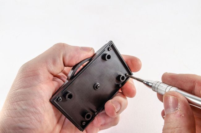 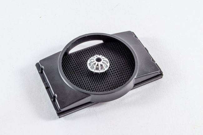 STAGE 67: FRONT OF THE RADIATOR STAGE 67: FRONT OF THE RADIATOR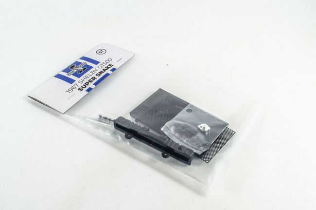 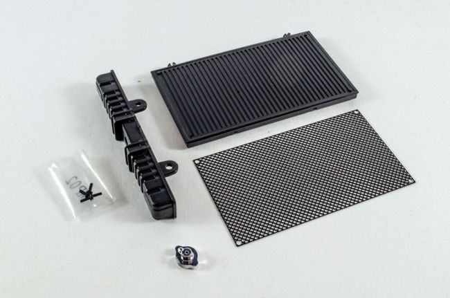 First, the radiator cap is screwed to the radiator top... 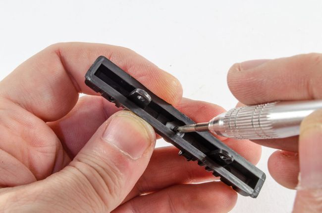 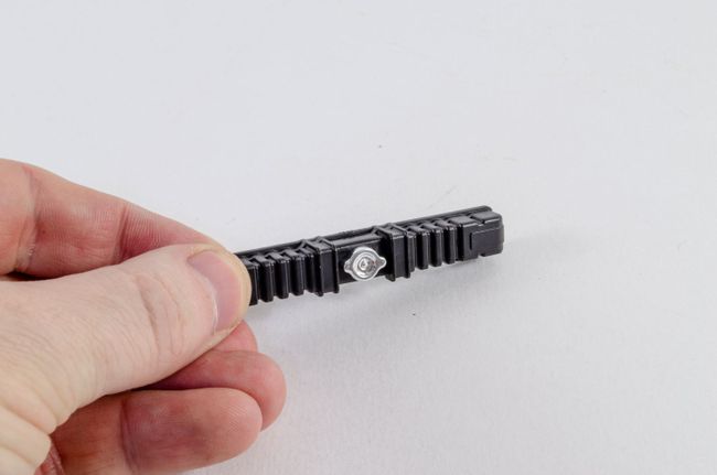 ...and then the top os sandwiched between the new radiator front and the assembly already built. These just click together tightly and need no screws or glue. 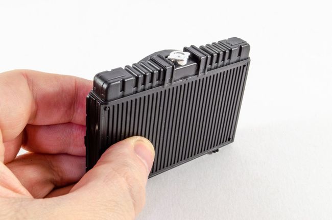 The next grille is then secured to the front radiator panel. 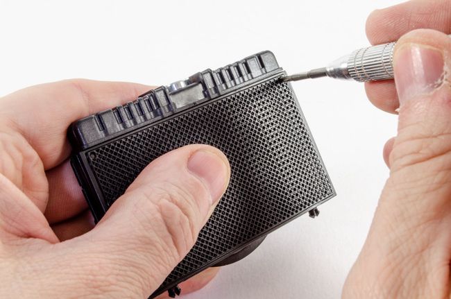 STAGE 68: ENGINE PARTS STAGE 68: ENGINE PARTS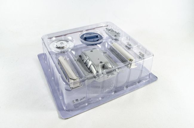 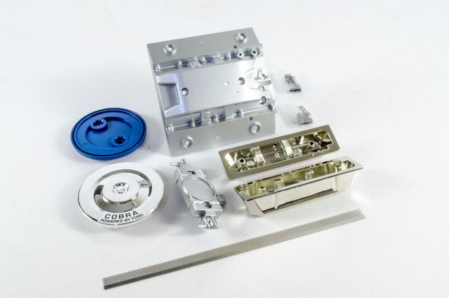 The first thing to go here is to curl the photo-etch air cooler grill around the inside lip of the air filter base. There is a red stripe on the mesh and this needs to be outwards and sat in the base. You'll still see a little of this when assembled. This task is quite easy to do and you don't need to curve the mesh beforehand. 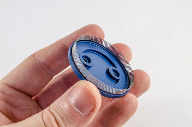 The air filter top is now added and screwed into position. 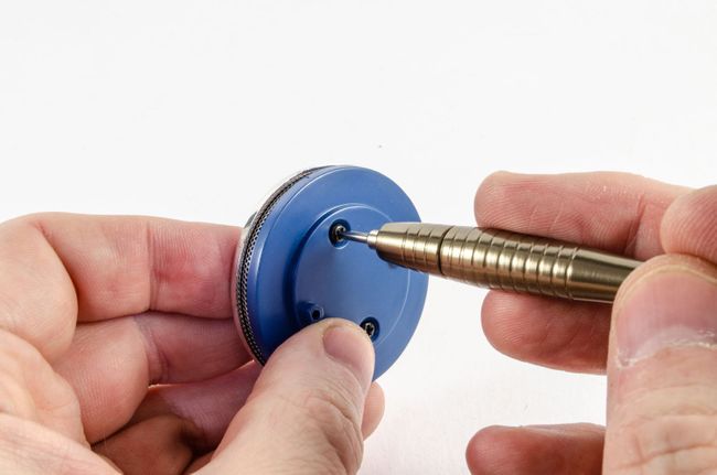 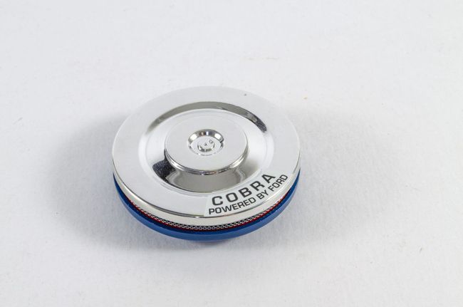 The carburettor is now screwed to the underside of the air filter, and the complete assembly then screwed to the cylinder head cover. 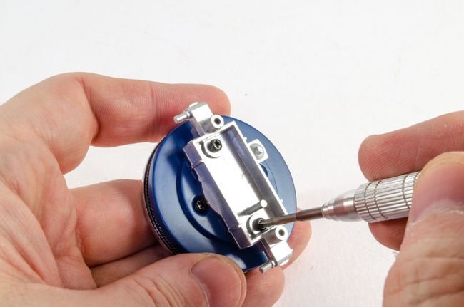 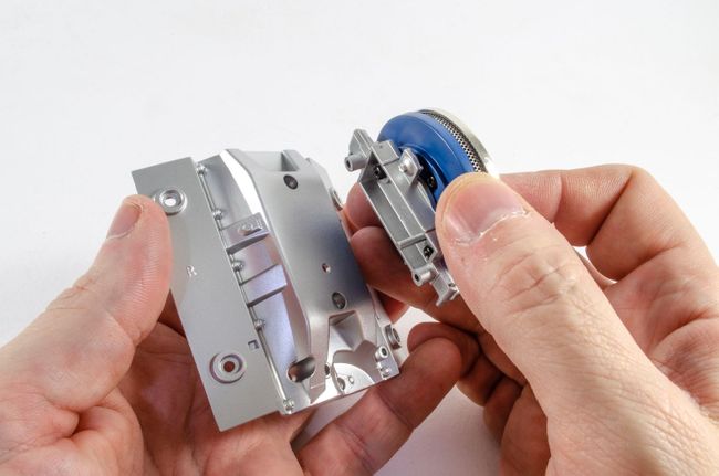 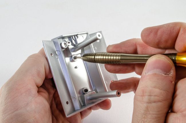 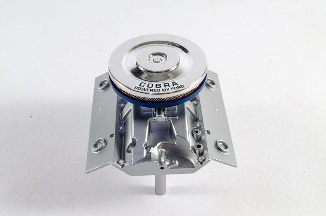 The beautiful, chrome finished valve covers are now screwed into position. These are marked 'L' and 'R' and are notched so they fit the right war around. 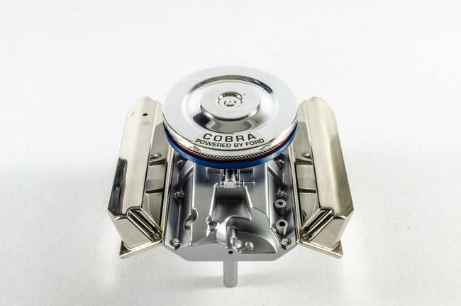 STAGE 69: FRONT HOUSING AND PRESSURE PUMP STAGE 69: FRONT HOUSING AND PRESSURE PUMP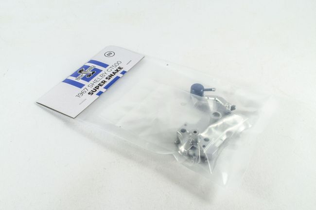 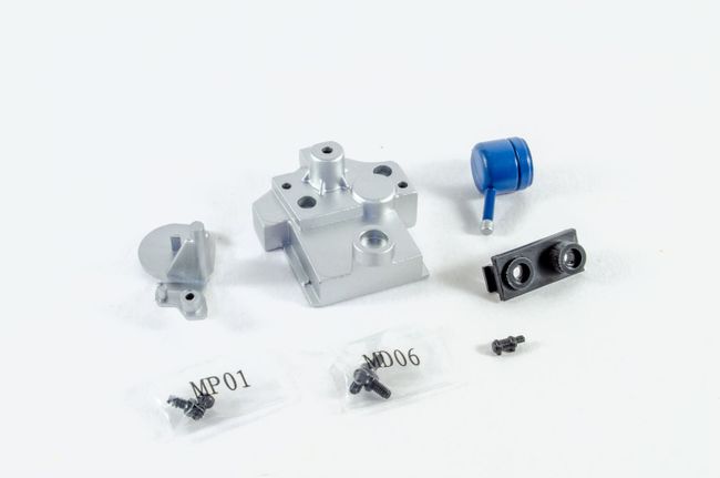 The housing support is screwed to the engine's front housing. 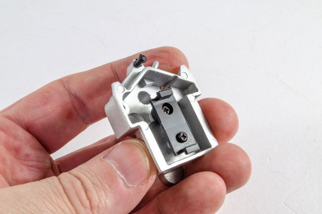 The pressure pump is now pushed on its support. No glue needed. 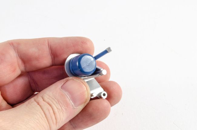 The two assemblies are then screwed together. 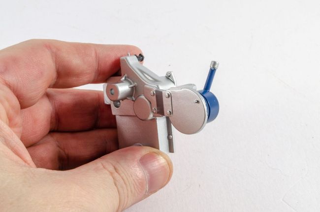 STAGE 70: ALTERNATOR, PULLEYS AND RADIATOR HOSE STAGE 70: ALTERNATOR, PULLEYS AND RADIATOR HOSE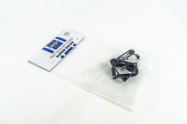 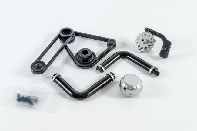 First up is to push the alternator onto its support. Again, this is a friction fit, so no glue needed. 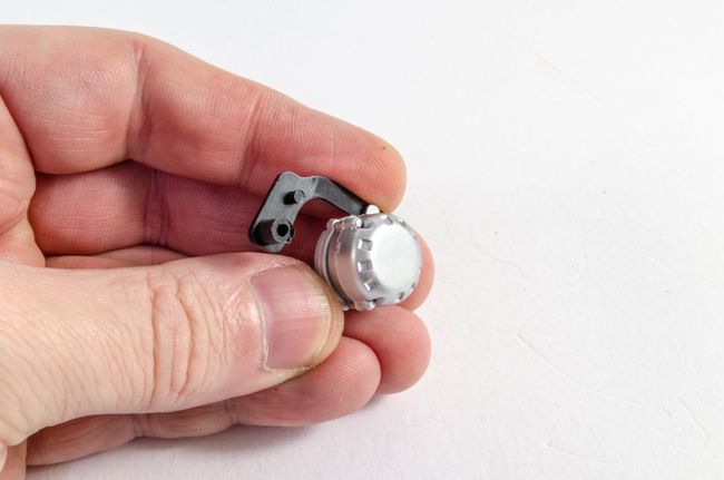 The radiator hose parts are also just squeezed together. 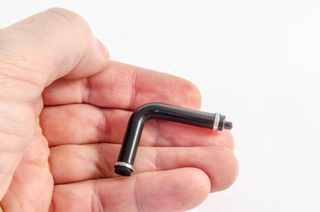 A single screw fastens the alternator support to the engine front. 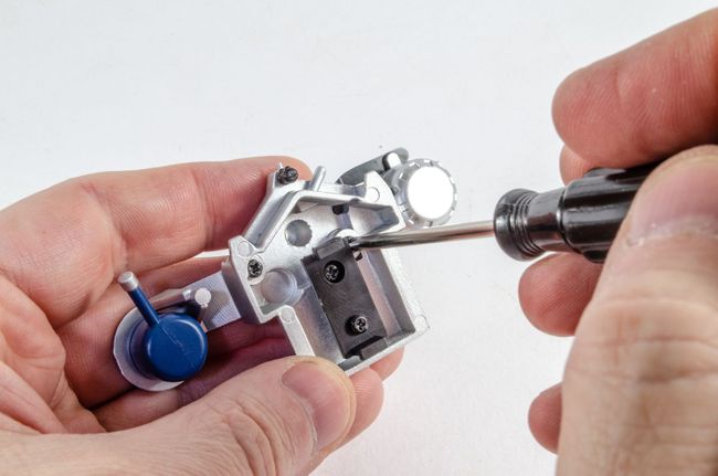 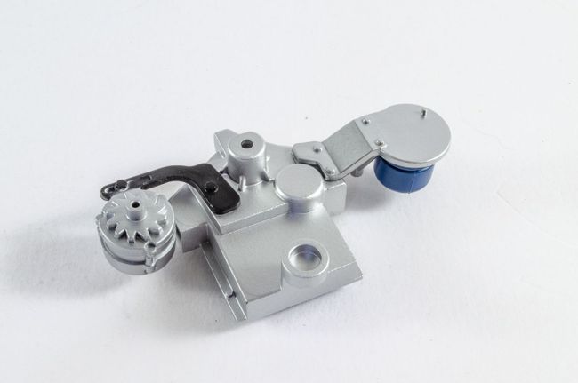 No glue is needed for fitting the pulleys either. The fit is very good and really won't come off! 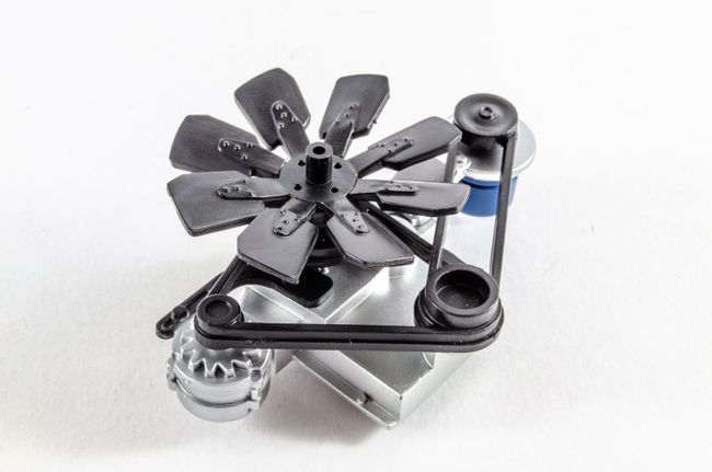 The radiator hose is then pushed into the radiator unit. 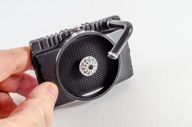 STAGE 71: ENGINE BLOCK, RIGHT EXHAUST MANIFOLD AND LIGHT SWITCH STAGE 71: ENGINE BLOCK, RIGHT EXHAUST MANIFOLD AND LIGHT SWITCH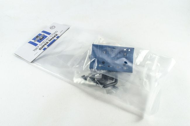 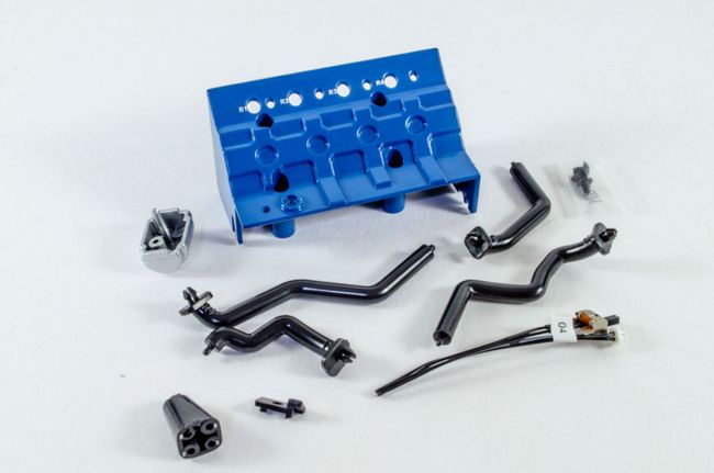 Some heavy metal work again as the gas filter is screwed to the engine right half. 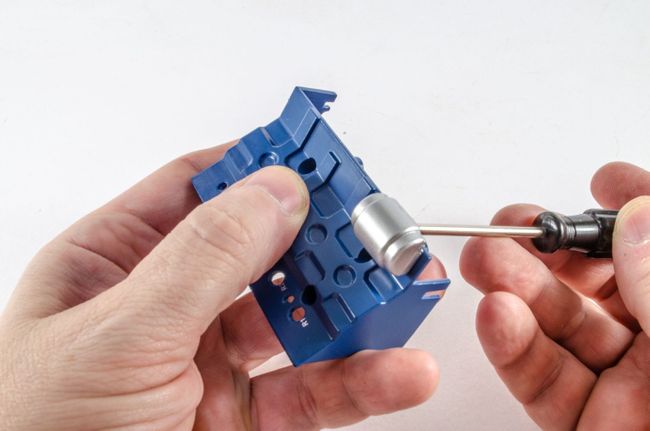 Over to the car interior for a moment. The light switch is fastened as shown, with a small clip holding it in situ. This appears to hold it very well. 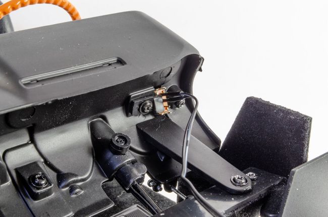 Assembling the manifolds is very easy. These are just a push fit and each is numbered. The manifold connector is also printed with the number locations and they can only fit in one way. 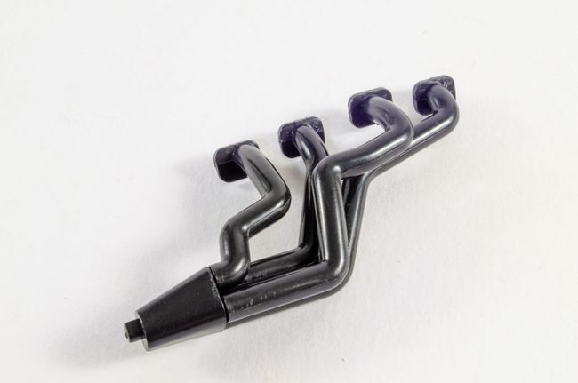 STAGE 72: LEFT ENGINE BLOCK, EXHAUST MANIFOLD, GEAR BOX AND RADIATOR SUPPORT STAGE 72: LEFT ENGINE BLOCK, EXHAUST MANIFOLD, GEAR BOX AND RADIATOR SUPPORT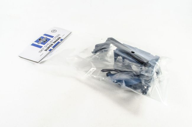 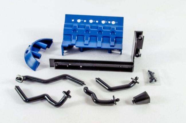 Fitting the engine front to the left engine block was a little problematic as the plastic part on the rear of the engine front, wouldn't push full home. I used a small file to open up the slots on both the engine block sides, and that fixed the problem. 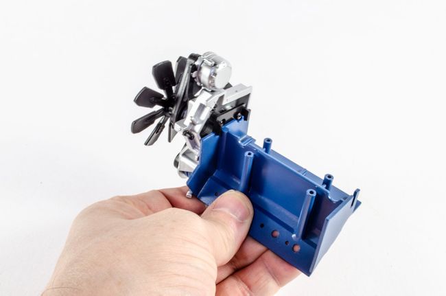 Whoops, note I added the curved gear box part the wrong war round? That was changed after these photos were taken. 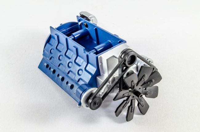 Both manifolds are now clipped into the engine block. 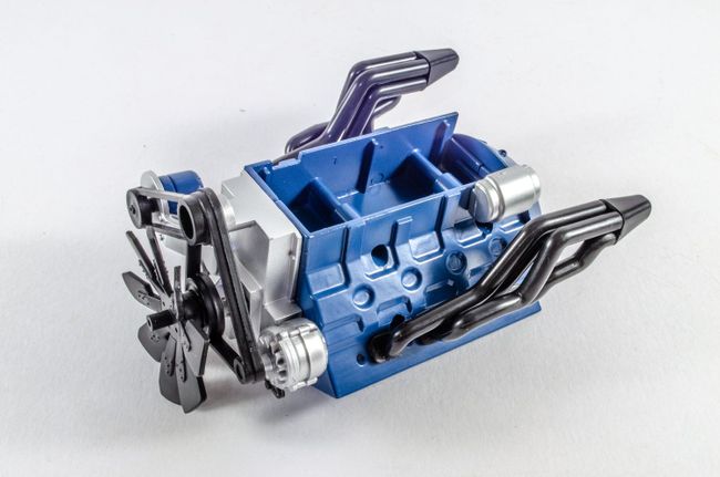 Another push fit sees the radiator support bracket fitted to the completed radiator unit. 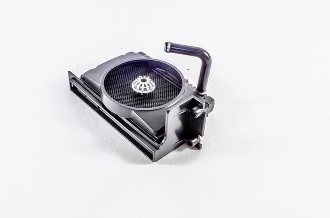 STAGE 73: ENGINE BLOCK BOTTOM, OIL COOLER AND CONNECTION CABLE STAGE 73: ENGINE BLOCK BOTTOM, OIL COOLER AND CONNECTION CABLE 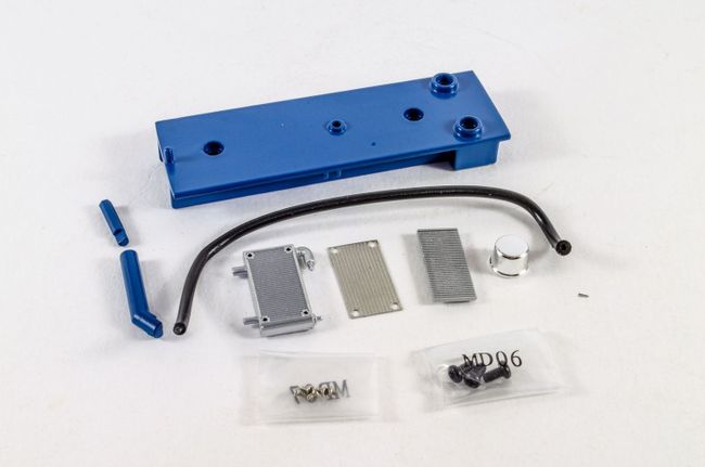 The large chunk of metal and its assemblies that built up the upper engine, is now slotted into the engine housing and the engine bottom plate screwed into place. 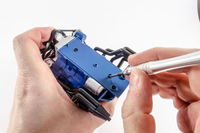 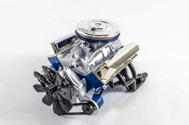 Filler pipe, pressure probe and connection cable are now added. 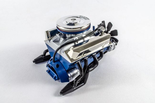 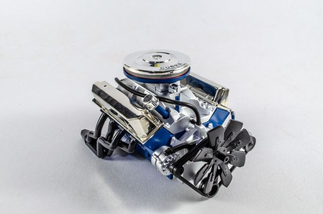 The oil cooler is now assembled and fastened to the radiator unit. 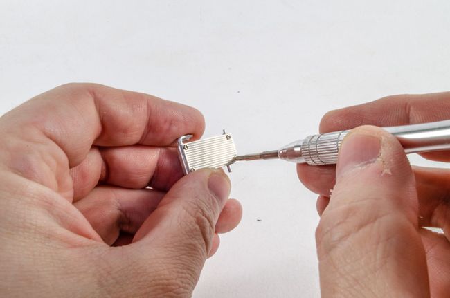 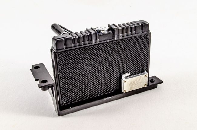 More next time!
|
|
|
Rank: Semi-Pro Level 2 Groups: Registered
Joined: 11/01/2017 Posts: 89 Points: 259 Location: Lancashire, UK
|
Pack 10Well, we are definitely creeping close to the finish line after this package, and this one comes in a reasonably large and heavy box due the inclusion of the fenders. As she sits now, this is one imposing model. Agora have left a teaser too with the fenders not being fitted during Pack 10, but presumably waiting for next month until we can see things coming together for the exterior. And with this pack...we have wiring! Not sure what battery this will use though. STAGE 74: DISTRIBUTOR, SPARK PLUG WIRE AND OIL PAN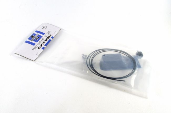 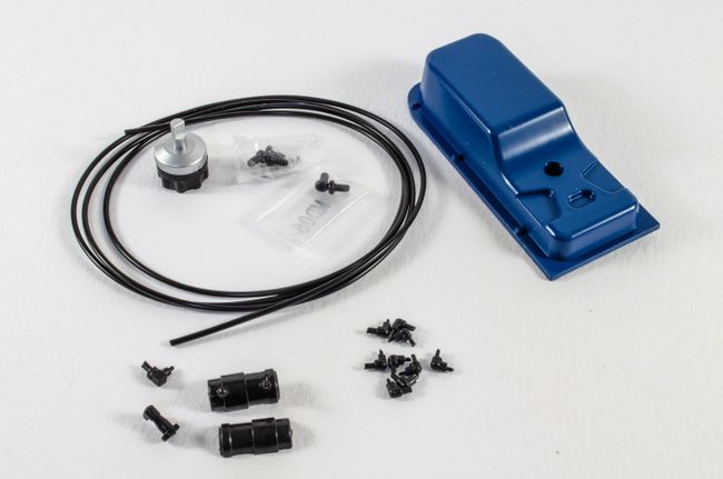 The ignition coil is built from three parts which just push fit together. No glue needed here at all. The same goes for mounting it to the engine, and it will only fit one way too.  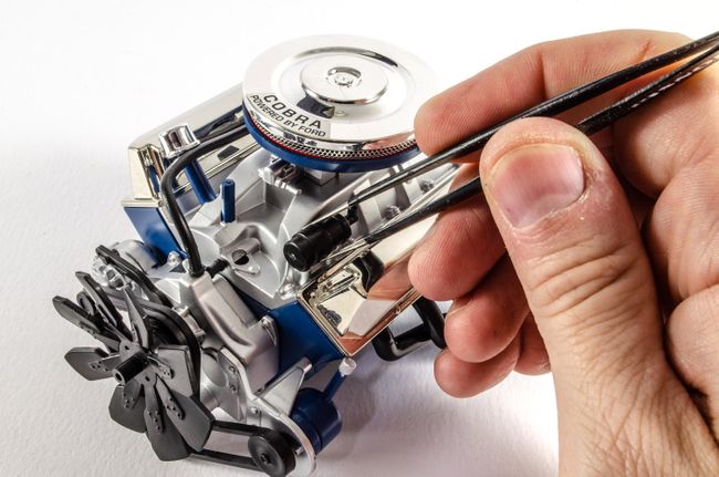 Plumbing the engine issues quite therapeutic and the suggested sequence of plumbing works well too. The vinyl hose needs to be cut to different lengths before being connected between the distributor and the main body. Everything is nicely colour coded in the instructions, so it's very hard to get wrong. I did use a little spot of CA between the hose/wire and the spark plug connectors as they did come off fairly easy. The oil pan was also fitted, though in hindsight, it would have been easier fitting that before the spark lines. 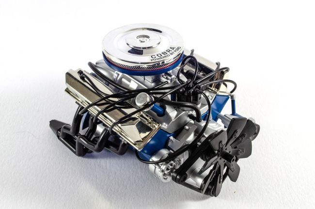 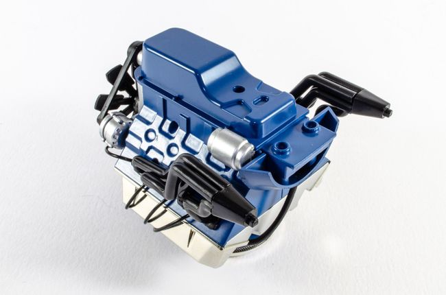 The beast can now be mounted into the chassis. For this, there's only two screws, but as the engine compartment builds up, everything becomes real sturdy. 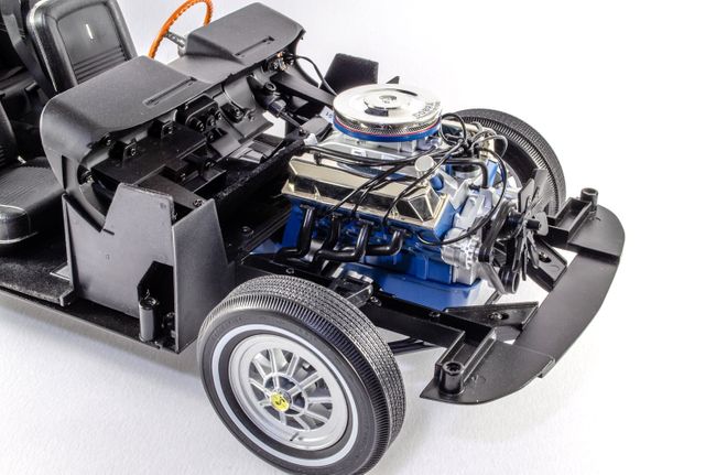 STAGE 75: SIDE PANEL AND FRONT RIGHT SHOCK ABSORBER STAGE 75: SIDE PANEL AND FRONT RIGHT SHOCK ABSORBER 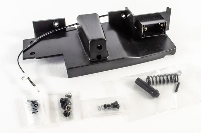 The right hand shock absorber piston is fastened to the car by means of another serrated pin. The radiator is now fastened to the side panel, and the piston body itself now screws to the outside of the right side panel. Onto the latter slides the shock absorber spring and then the whole unit is carefully lowered into position so the piston fits to the piston body. A little tricky, but not too difficult. Two screws hold the side panel securely in place. 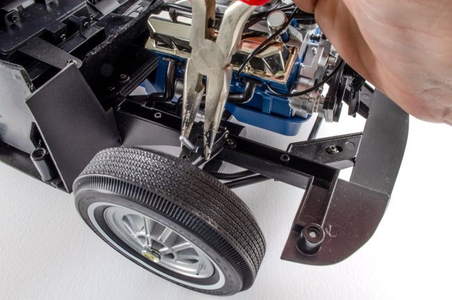 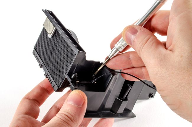 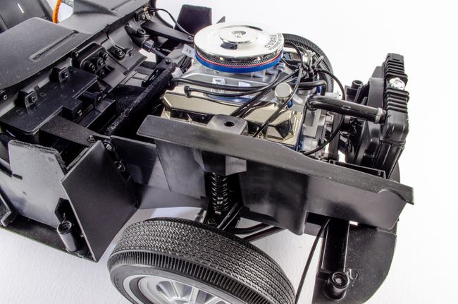 STAGE 76: ENGINE CENTRAL PANEL, PUMP AND BRAKE FLUID RESERVOIR STAGE 76: ENGINE CENTRAL PANEL, PUMP AND BRAKE FLUID RESERVOIR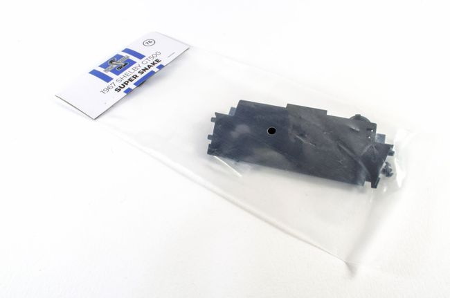 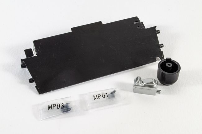 This one is dead simple. The brake fluid reservoir is push fitted to the support snd the completed assembly screwed to the right hand engine bay wall. Care is needed not to trap any cabling under this wall, and the side screws mean you'll need to manipulate some of the surrounding parts to be able to get a clear shot. 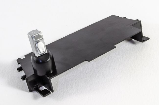 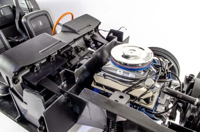 STAGE 77: FRONT LEFT PANEL, SPEAKER AND SUSPENSION STAGE 77: FRONT LEFT PANEL, SPEAKER AND SUSPENSION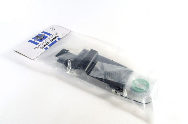 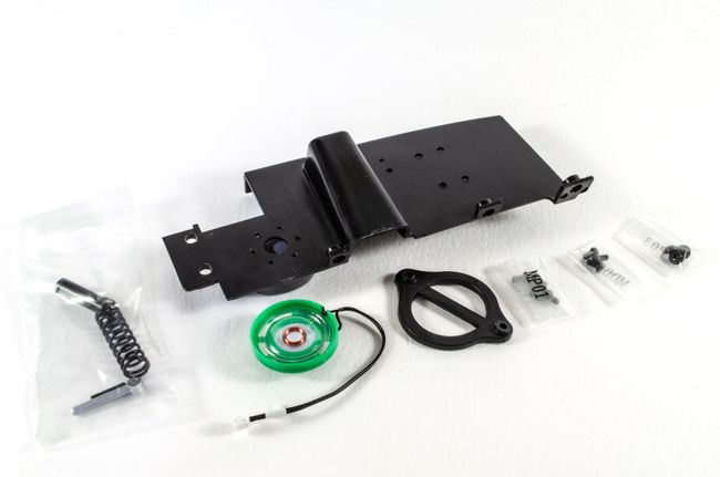 It's now the turn of the left hand engine bay wall too be fitted. This is done in the same way as the first except the speaker needs to be fitted first and the retainer/support screwed into place to trap it. Care needs to be taken to ensure the wires flow from the recess properly. 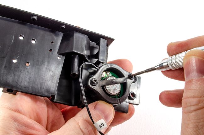 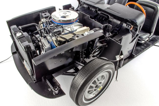 STAGE 78: BATTERY, STRUT BAR, WATER PUMP AND PIPES STAGE 78: BATTERY, STRUT BAR, WATER PUMP AND PIPES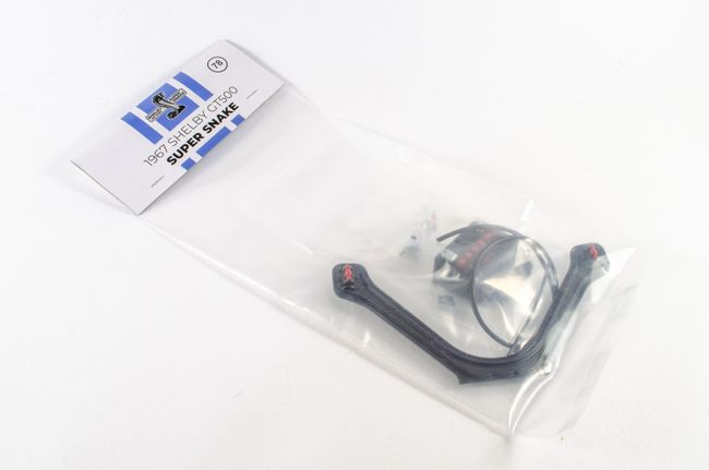 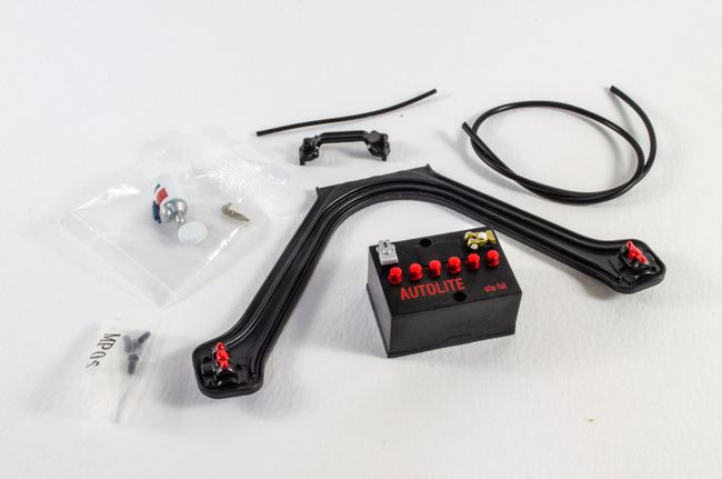 Almost everything in this pack is a push fit. The handle is first attached to the battery with the only screws to be used here. This needs to be a sold fit as the battery lifts out to reveal the actual battery pack for the car's electronics. 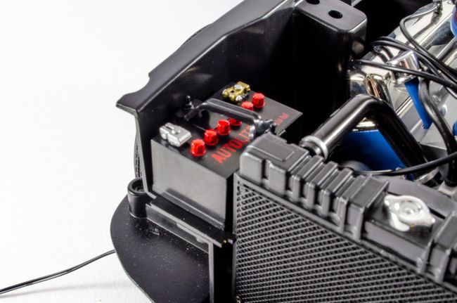 The oil filter can now be built and plumbed in, as well as the strut bar being attached. This makes everything quite rigid. 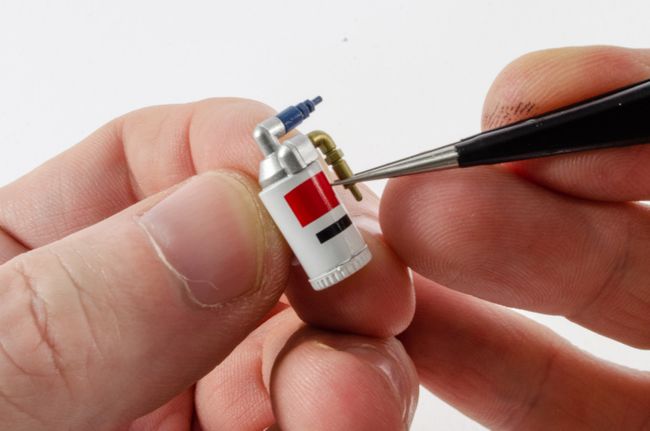 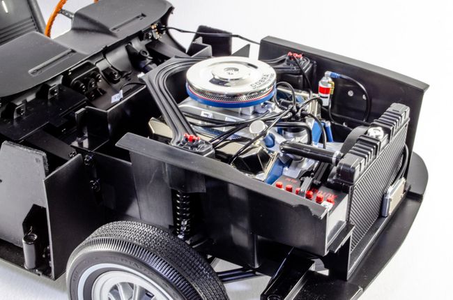 STAGE 79: WASHER FLUID RESERVOIR, ELECTRONIC CIRCUIT AND WIRING STAGE 79: WASHER FLUID RESERVOIR, ELECTRONIC CIRCUIT AND WIRING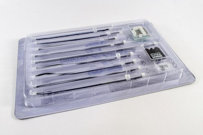 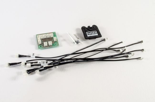 It seems ages ago since we looked at any electronics, but here I get to plug the supplied cables into the circuit board. These are all numbered both on board and cable with only one board socket remaining free (06), which accommodates the speaker we recently fitted. 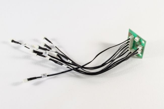 The board is now screwed into position as seen and the cables fed through various channels. I started with the cable the furthest away from the channel as I didn't want to end up with a rat's nest of untidy wiring. Cables 01, 02, 03, 04, and 05 are now connected to the various sockets that run from the battery box, steering column, lights, pedal etc. The speaker is also plugged into socket 06 on the circuit board.The windscreen washer fluid bag is also pushed into place next to the oil filter. 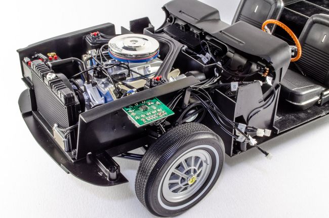 STAGE 80: LEFT FRONT FENDER STAGE 81: CHASSIS FRONT PANEL STAGE 82: RIGHT FRONT FENDER STAGE 80: LEFT FRONT FENDER STAGE 81: CHASSIS FRONT PANEL STAGE 82: RIGHT FRONT FENDER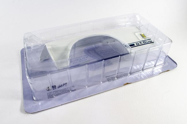 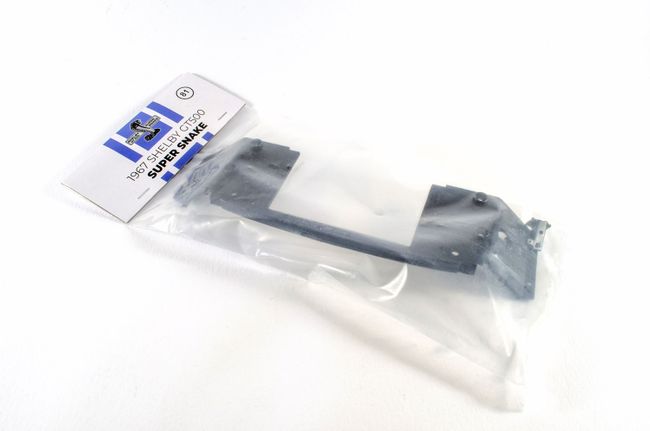 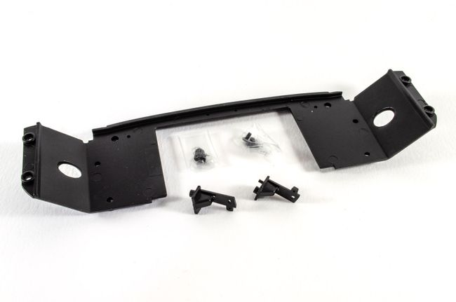 Not too much to write about here except both fenders are now screwed to chassis front panel after the hood supports are fitted. 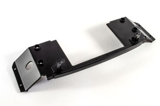 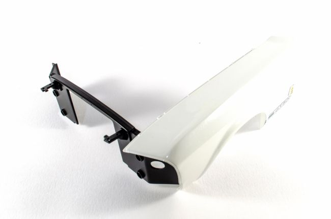 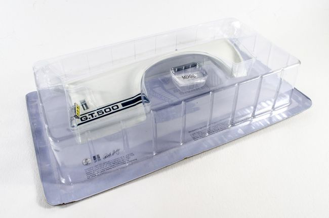 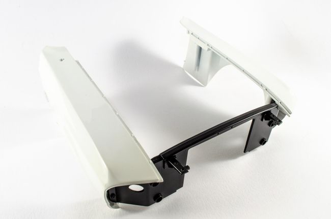 Until Pack 11, that's it!
|
|
|
Rank: Semi-Pro Level 2 Groups: Registered
Joined: 11/01/2017 Posts: 89 Points: 259 Location: Lancashire, UK
|
Pack 11 - almost there!By far the LARGEST box to yet arrive from Agora, but hardly surprising when you consider it contains the GT500's main body. This is also a heavy box too as the largest components are metal, such as the body, hood and trunk etc (bonnet and boot, to us Brits!). There's no worry about this arriving in one piece either as the main body is contained inside a secondary bod, packed into dense polystyrene. The other packs are sat on top of this, with some of them now being blister packs again, and not just sleeves. Here's how things look when it arrives: 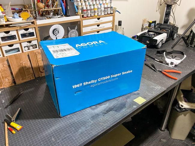 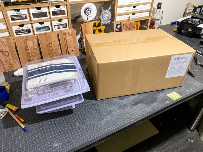 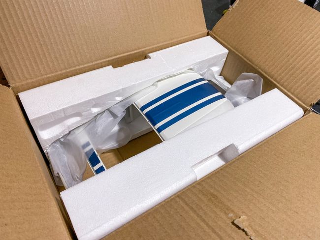 STAGE 83 : MAIN BODY SECTION STAGE 84: UPPER & LOWER SIDE SCOOPS STAGE 83 : MAIN BODY SECTION STAGE 84: UPPER & LOWER SIDE SCOOPS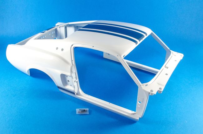 This one is quite simple. Before any work started, I used some protective foam to cover the paint stripes as they can be easily damaged when working. The model was also laid on a bed of bubble wrap for extra insurance. 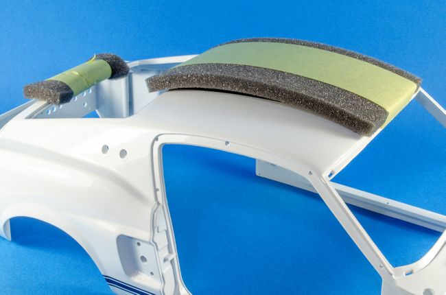 The fender assembly is now fastened to the main body by four screws. 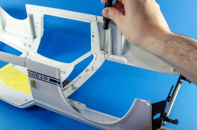 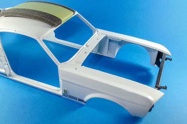 STAGE 84: UPPER & LOWER SIDE SCOOPS STAGE 84: UPPER & LOWER SIDE SCOOPS Another simple stage now as the air vents/scoop are fastened to the exterior. There's no way you can get these wrong due to the shapes involved and the recesses for the lower scoops. These actually look real nice and add some extra character to the main body. 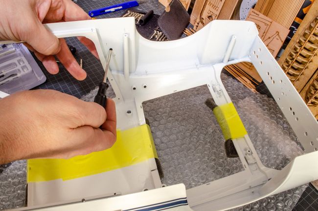 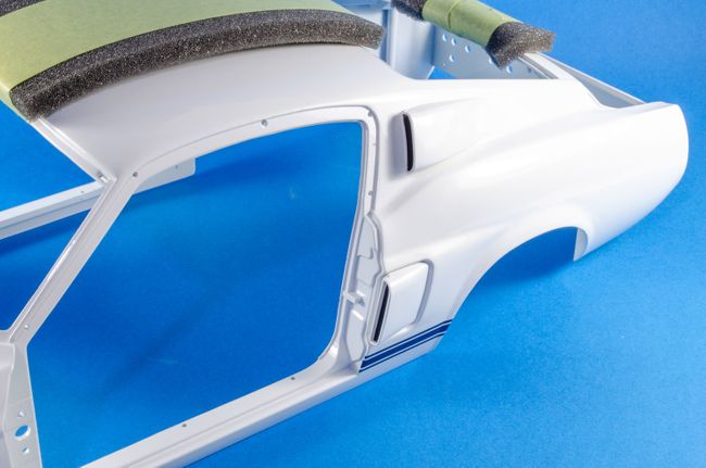 STAGE 85: HOOD, FRONT GRILLE, HIGH-BEAM HEADLIGHTS STAGE 85: HOOD, FRONT GRILLE, HIGH-BEAM HEADLIGHTS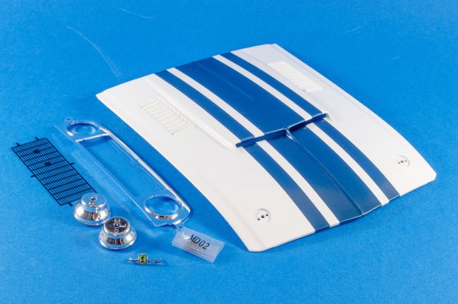 To attach the Shelby logo to the front grille, two little tabs need to be bent inwards. These then snag onto the badge locating pins, holding it in place. 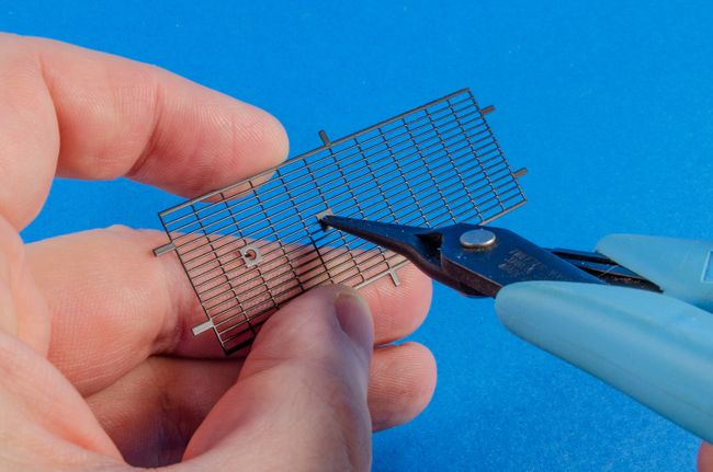 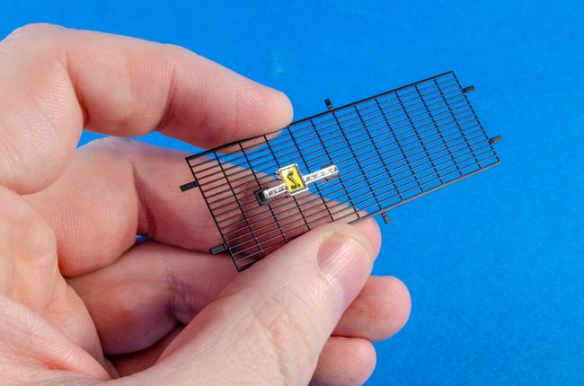 The other tags now need to be bent inwards, fully. The grille can then be fitted to the grille surround, and the tags then bent backwards to lock the grille into its surround. The surround is then screwed to the front Cobra assembly. 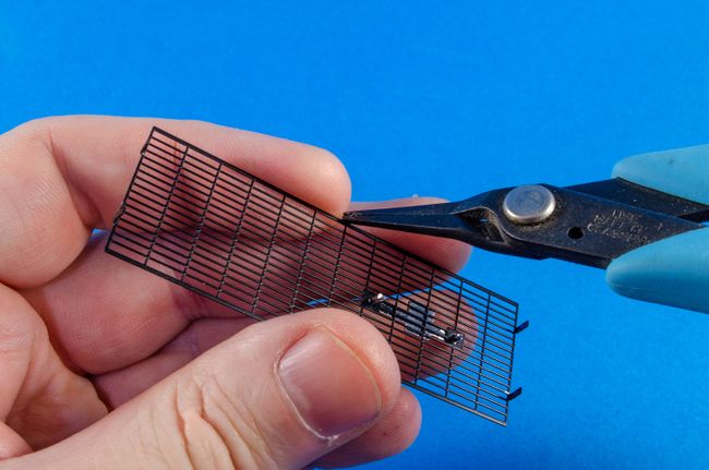 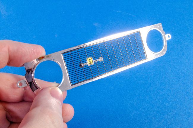 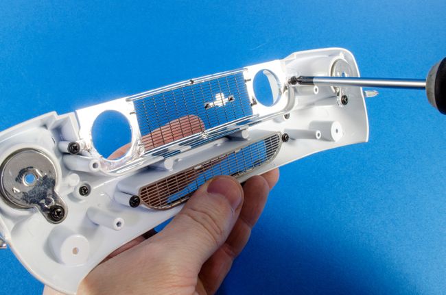 The next thing to fit are the headlights which just push into the grille surround from the front. The screw position needs to be pointing upwards so they are angled correctly. 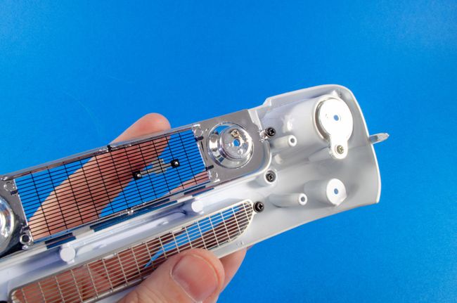 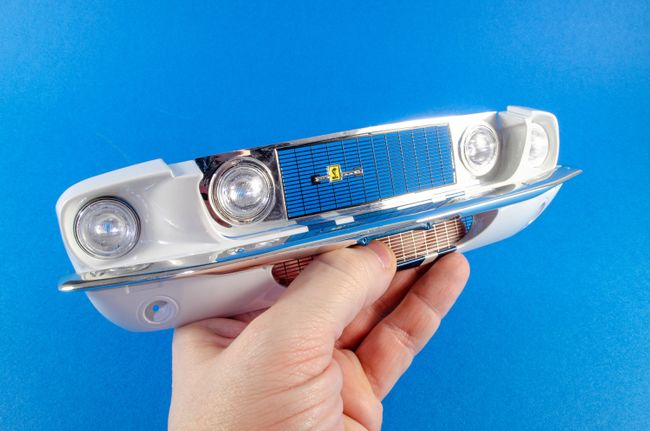 STAGE 86: HOOD HINGES STAGE 86: HOOD HINGES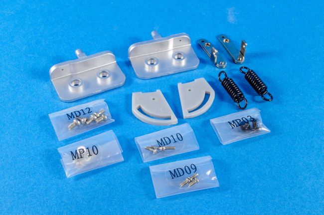 The hood hinges are now fitted to the hood. There are three different types of screw used for this, so care needs to be taken to get this right. There's quite a lot of tension in these when built, and it's a good idea not to keep operating these until fitted to the car as the slider won't cleanly operate until then. 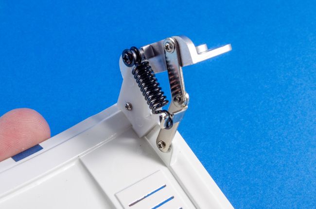 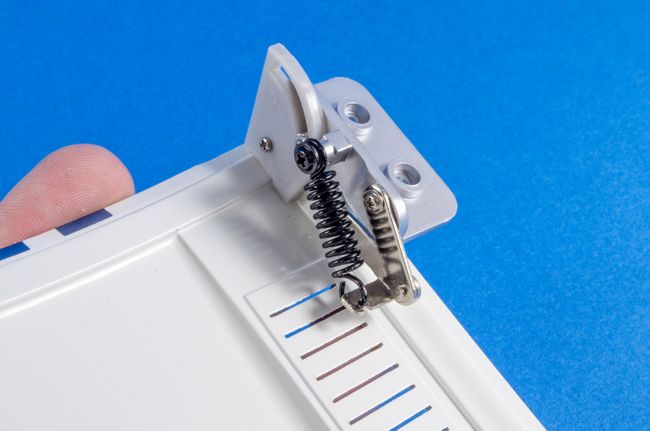 Four screws now secure the hood to the main body. The hood needs to be inserted an an angle and then slid upwards at the rear to locate it. I had to move the hinged slightly to get this into position. I also noticed that the hood wasn't even to the fenders on each side, so the fenders needed to be slackened off and realigned to the hood. 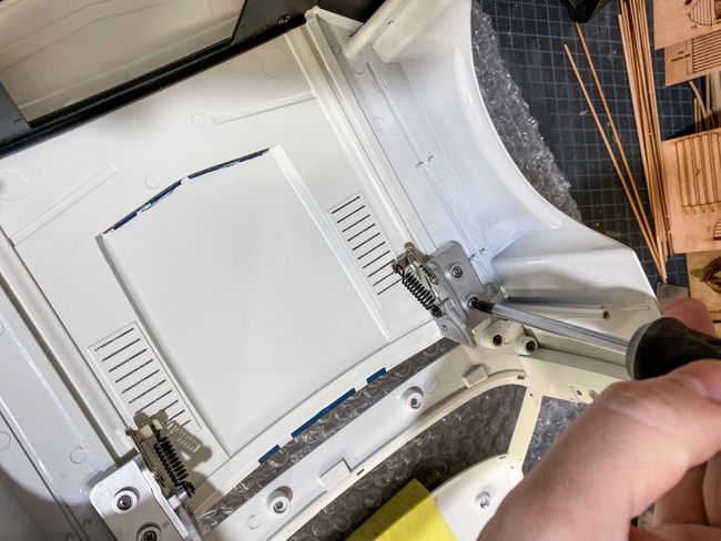 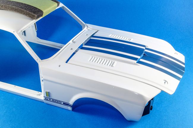 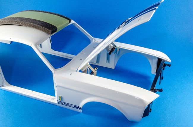 STAGE 87: CENTER LIGHT BRACKET, HORNS, HOOD PINS, FOG LIGHT LENSES, LED SYSTEM, WIRE HOLDERS STAGE 87: CENTER LIGHT BRACKET, HORNS, HOOD PINS, FOG LIGHT LENSES, LED SYSTEM, WIRE HOLDERS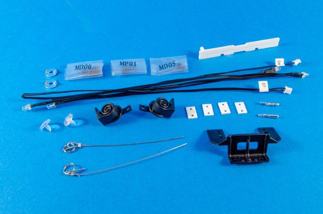 The centre light bracket and holds are fastened to the front bracket. The hood pins are now pushed into place and the hood closed to ensure they located through the holes in the forward hood. I found the hood would then snag them and pull them out again, so I used a little CA to fasten the pins. 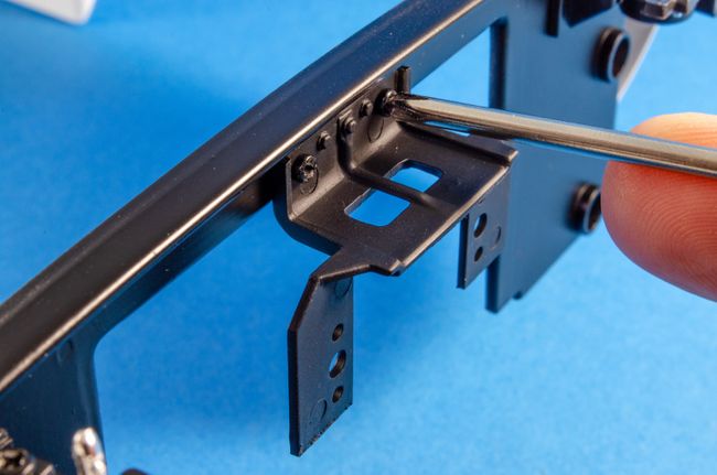 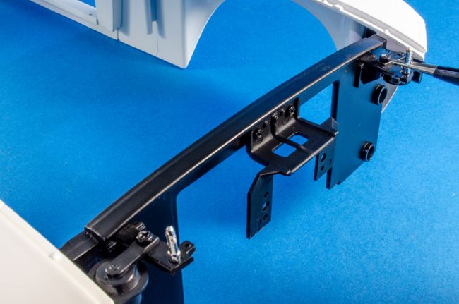 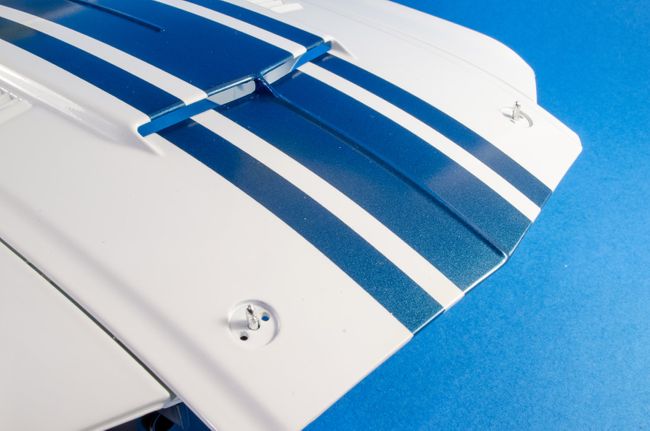 Now the headlights can be wired up, with wire 07 to the left, and 08 to the right. A cable tidy helps hold the wires in place when installed. 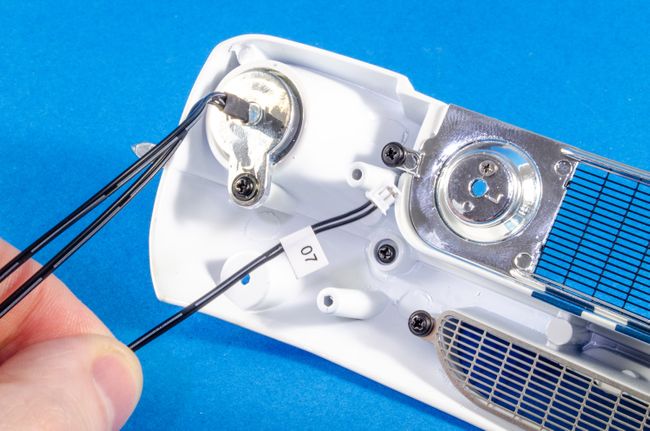 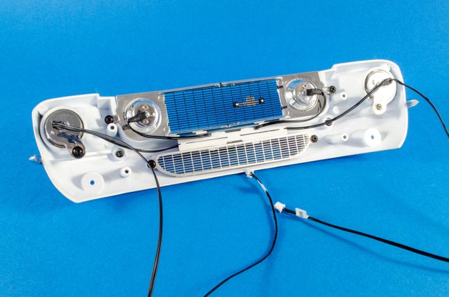 Some white glue (PVA) is used to fit the fit lights. I didn't use CA here as it can fog clear plastic. 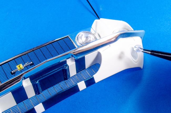 The front is then offered up to the main body and screwed into position, making sure the headlight cables fit neatly through the holes in the front bracket. The cables are then run through the. body channels and held into position with wire clips. I wasn't very confident that those clips wouldn't later come loose so I used a tiny spot of CA to hold them in place. 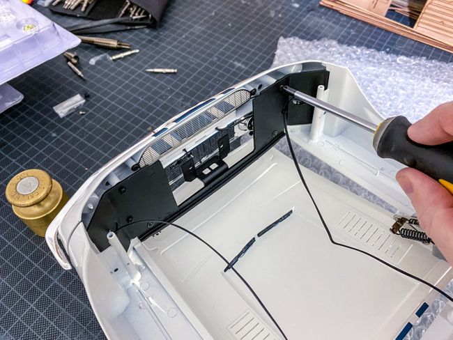 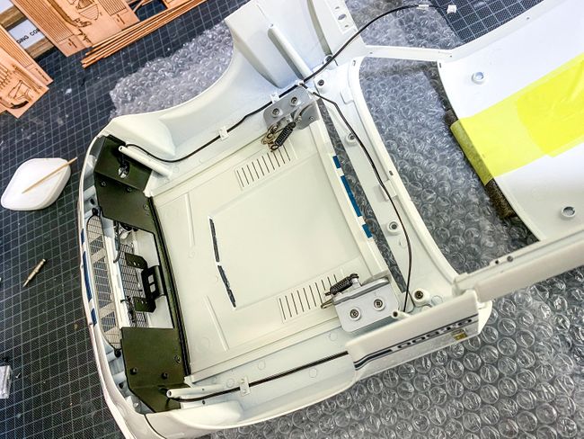 The hood pin plates are now pushed into position and the lanyards/Lynch pins attached. 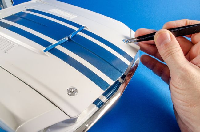 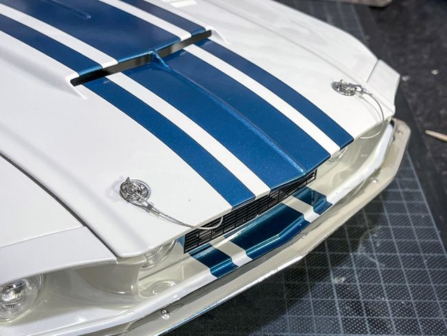 STAGE 88: TRUNK LID, LOCK AND SHELBY EMBLEM STAGE 88: TRUNK LID, LOCK AND SHELBY EMBLEM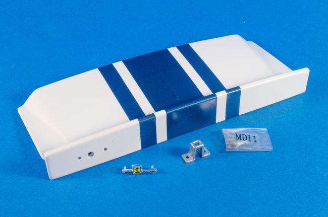 The trunk lock and Shelby emblem are now fitted to the trunk lid. 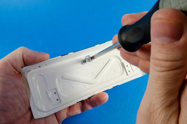 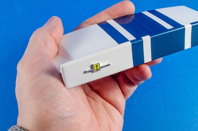 STAGE 89: LOWER REAR BODY SECTION, TRUNK HINGES AND BRACKETS STAGE 89: LOWER REAR BODY SECTION, TRUNK HINGES AND BRACKETS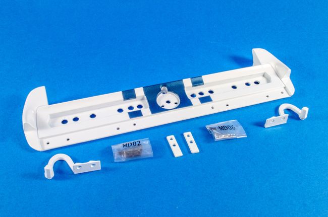 The lower rear body part is now offered up to the rear of the main body and secured with six screws. 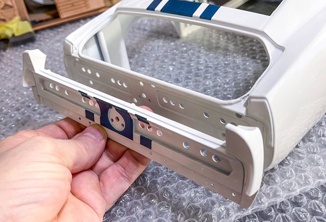 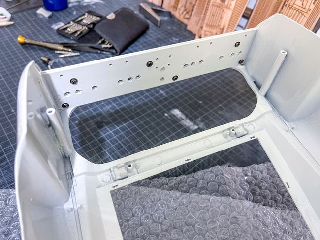 Both trunk hinges are fitted to the lid and the trunk led fitted to the main body, using the hinge brackets to hold in position. These are metal, so no chance of them being bent with any force. 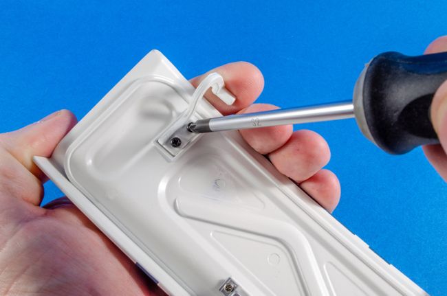 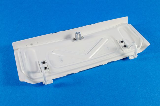 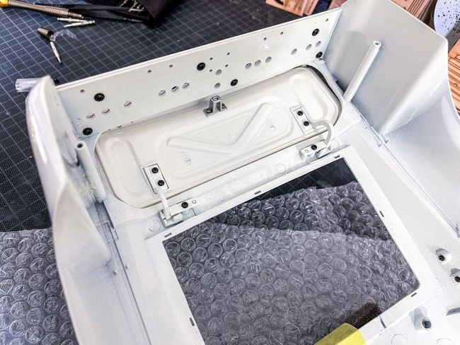 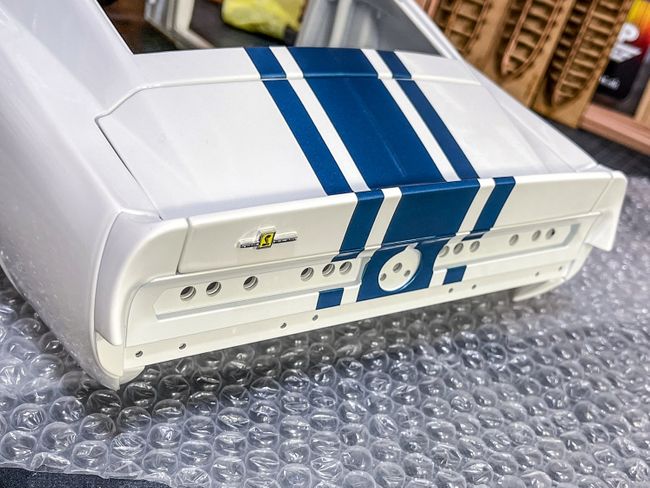 STAGE 90: REAR LIGHTS, LED WIRES, GAS CAP, GAS PIPE, CABLE HOLDERS STAGE 90: REAR LIGHTS, LED WIRES, GAS CAP, GAS PIPE, CABLE HOLDERS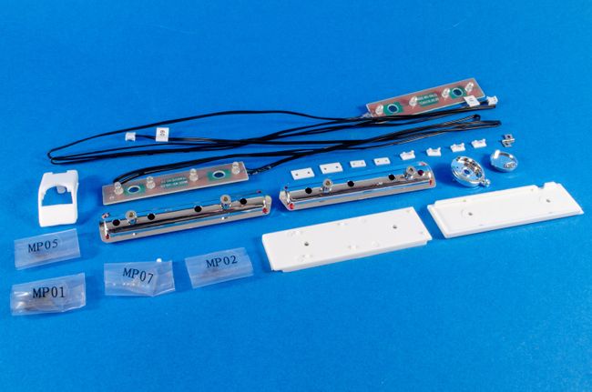 Before I can start the wiring, the gas cap and gas cap base are fastened together using the small hinge and shortest small screws. This is then pushed into position and secured with a screw. The gas pipe holder is then also fastened into position, using screws from the outside rear. 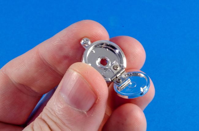 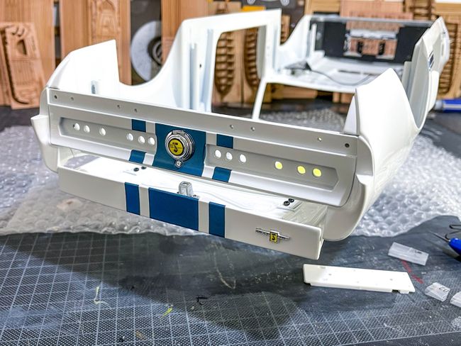 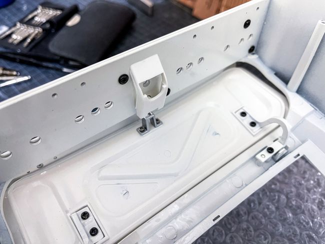 The right rear light is pushed into position... 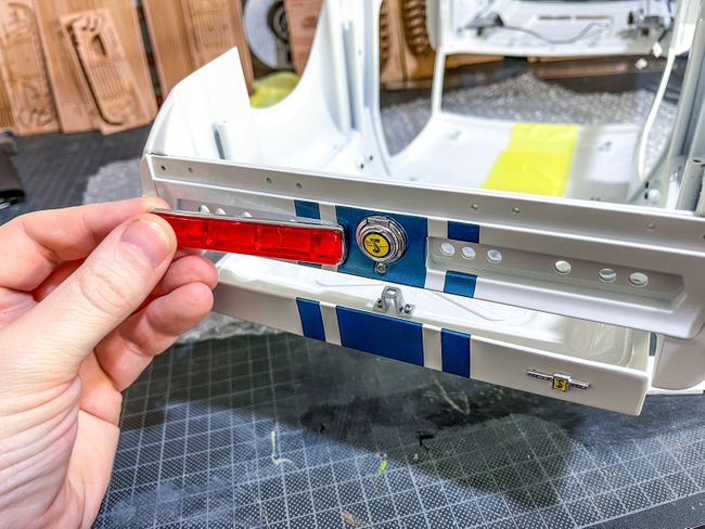 ...and the rear right LED strip popped into place. I did find that before I could fit the light holder, that I needed to clip down the LED tails on the soldered joints as they protruded a little too far and stopped the holder fitting snugly. 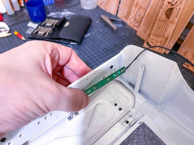 With the holder in place, the cable is run in its channel and the cable clips used to hold it down. Again, a spot of CA was used to make sure these didn't eventually come loose when everything is finally assembled. 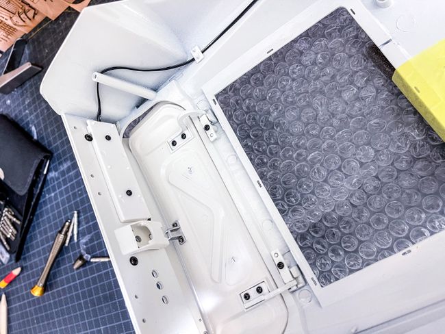 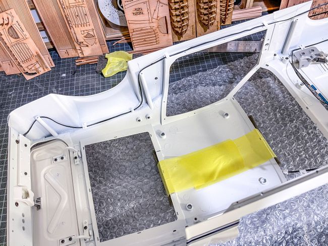 Things really are getting close to finish now. Here's where Pack 11 leaves us. 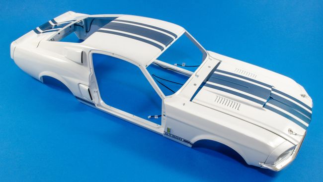 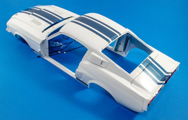 One more to go. I'm really hoping I see that pack before year end!
|
|
|
 Rank: Master  Groups: Registered
Joined: 25/11/2018 Posts: 1,284 Points: 3,878 Location: Southeast UK
|
Nice, tidy work James, looking good so far and I suspect this is going to be a very impressive model when complete?
Well done, keep up the good work. 
Kev.Per Ardua Ad Astra
|
|
|
|
Guest
|
 US
US

