|
|
 Rank: Semi-Pro Level 2   Groups: Registered
Joined: 11/01/2017 Posts: 89 Points: 259 Location: Lancashire, UK
|
Morning all! Adding to my current Shelby collection, is the beautiful Cobra. I was thrilled with the original Shelby GT500, but I already think this takes it to the next level. I'm also a sucker for the more classic looking car. Agora's new kit comes in their new style box which is designed to withstand the rigours of our postal system, so it arrived with me in great condition. Included with the kit is a large poster, cleaning cloth, and a screwdriver in the first pack of parts. This one is also magnetic, unlike the one in the GT500. 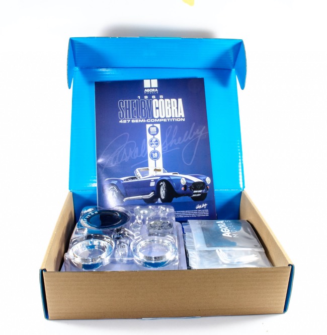 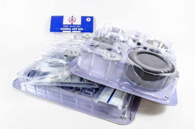 Pack 1Stage 1:Hood/Bonnet assembly Pack 1Stage 1:Hood/Bonnet assemblyAs a nice teaser, that very identifiable bonnet is part of the first to item to be built. I still have no idea why some call it a 'hood' 😆 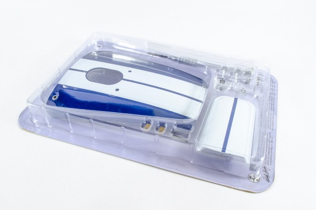 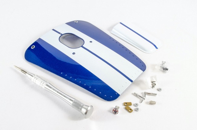 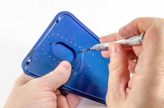 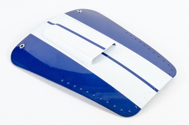 With this new model from Agora, it was reassuring to see that it has some proper sprung-loaded latches that also look extremely good. Yes, a little fiddly to assemble, but definitely a nice touch. Some neoprene tape is also added to the top edge of the bonnet to protect the bodywork from being marked. 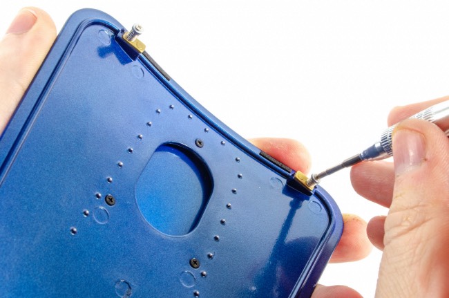 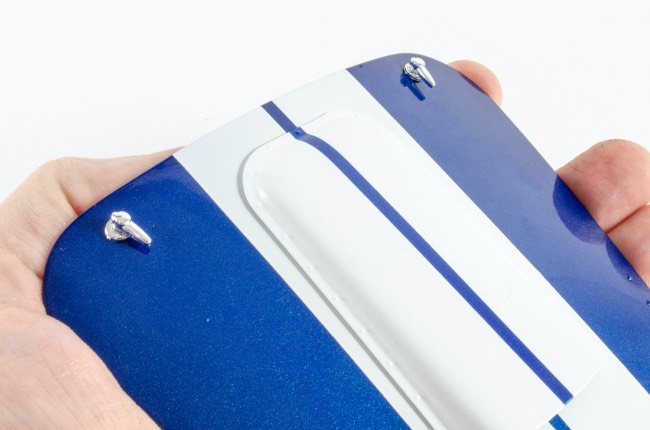 Stage 2: Left-leaning Front Wheel Stage 2: Left-leaning Front Wheel 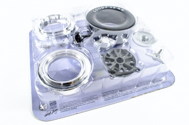 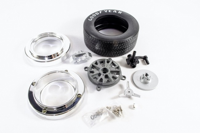 Unlike Agora's GT500, we get an early appearance from one of the wheels. With this one, the centre wheel section is sandwiched between the outer rims, as well as being firmly screwed into place. It's also vital that you soak the tyre in just-boiled water for around 5 minutes to soften it enough so you can fit the inner assembly in position. This one still took a little wresting but it does fit in the end. 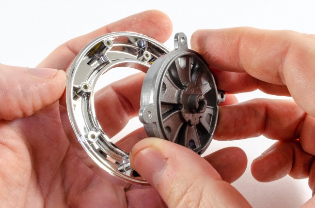 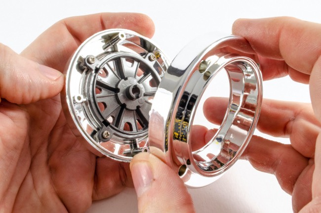 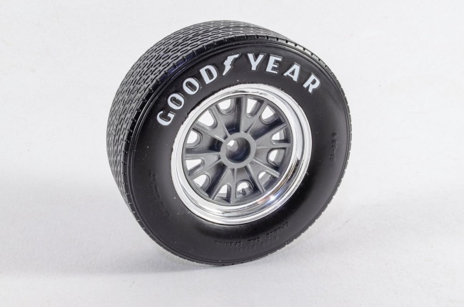 Now the wheel brake is assembled as shown, and a single screw holds the parts together. 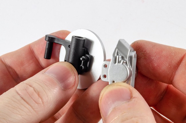 The brake assembly will only fit into the wheel in one position due to a slot system, and the wheel is secured from the outside using a screw. Be careful not to tighten too much or the wheel won't rotate. The hubcap is then pushed into the knock-on and this fasten my magic magnet to the wheel.  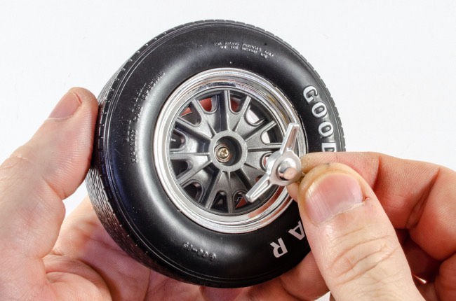 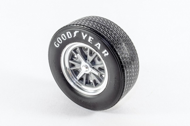 Stage 3: Steering wheel and exhaust parts Stage 3: Steering wheel and exhaust parts 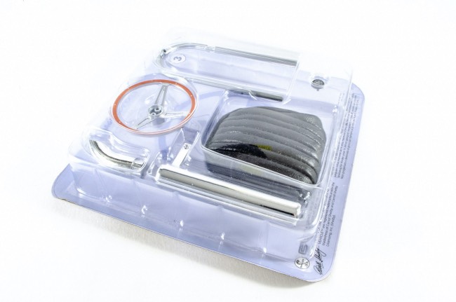 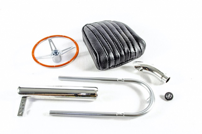 I'm not sure what the leather seat is made from, but it does feel like leather and is beautifully soft. 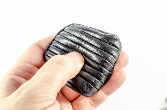 The steering wheel also has a realistic wood grain effect. The Cobra badge fits to the middle and will only fit the correct way around as the locating pips are different sizes. 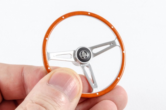 The exhausts are also a good fit and can only fit one way round. 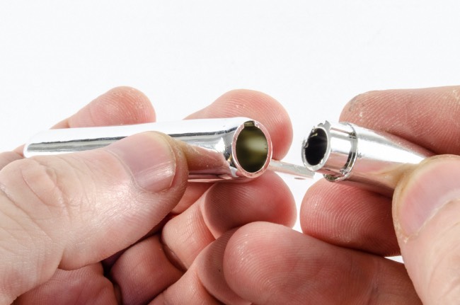 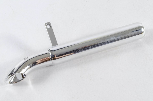 Stage 4: Engine & Exhaust Parts Stage 4: Engine & Exhaust Parts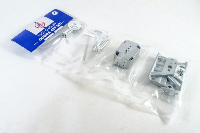 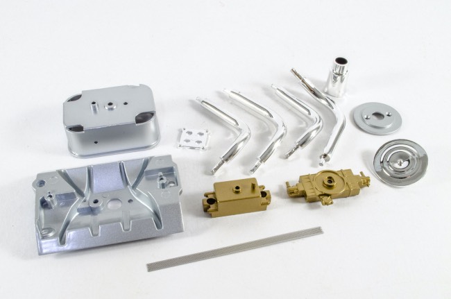 Perhaps the most fiddly part of this is curving the photo-etch edge of the air filter. To help, I first wrapped it around a small paint bottle and then inserted in the groove in the air filter top. This is all locked in place when the bottom is added. 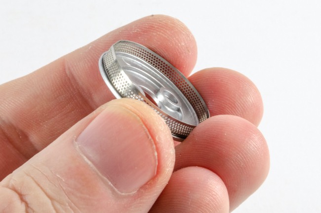 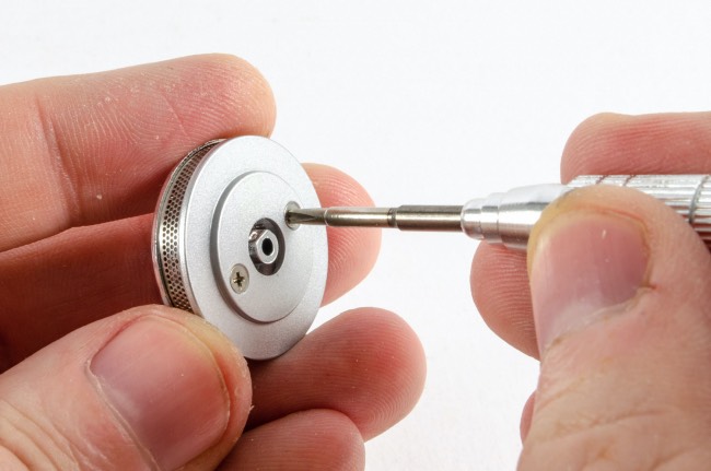 The carburettor bottom and top are now added and the whole assembly fitted to the engine block. 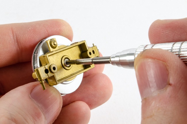 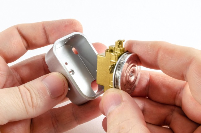 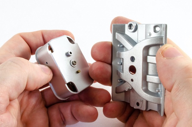 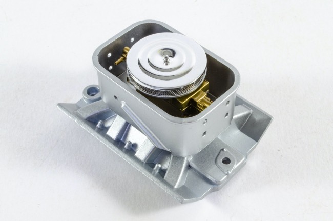 The exhaust manifold parts are numbered and plug into the main exhaust system. I found things fit a little easier by scraping away some of th chrome plating first. No glue was needed at all as everything was a very good fit. 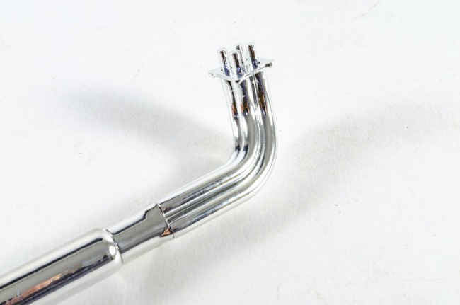 Stage 5: Oil Filter and Exhaust Parts Stage 5: Oil Filter and Exhaust Parts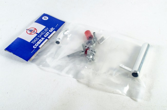 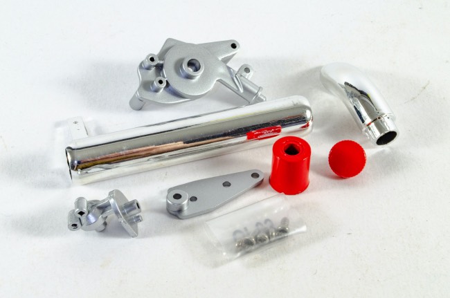 The oil filter is fitted to the bracket which then connects to the engine plate. There's not a lot to this pack as the exhaust parts are scheduled to be completed in the next stage. 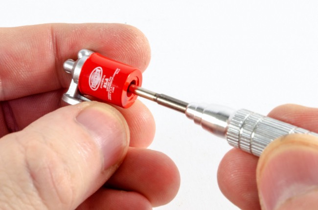 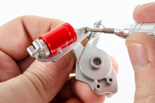 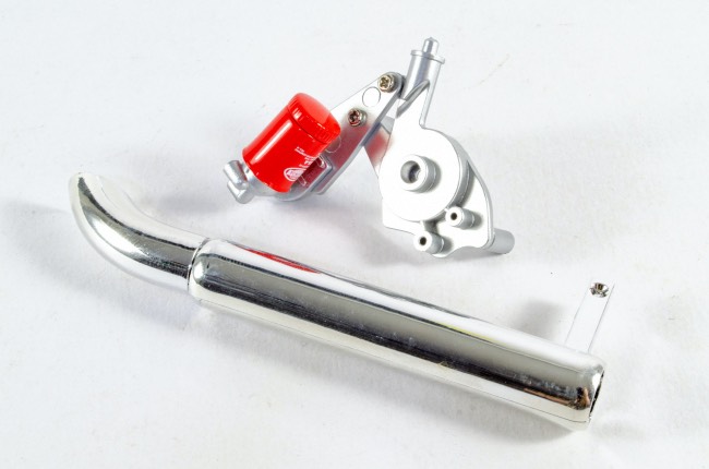 Stage 6: Exhaust Pipes Stage 6: Exhaust Pipes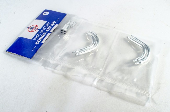 As with the first exhaust, the manifolds on this are assembled in the same way as the first, using the numbering system. This is a little fiddly but goes together quite well. Final adjustments can be made later in the build. 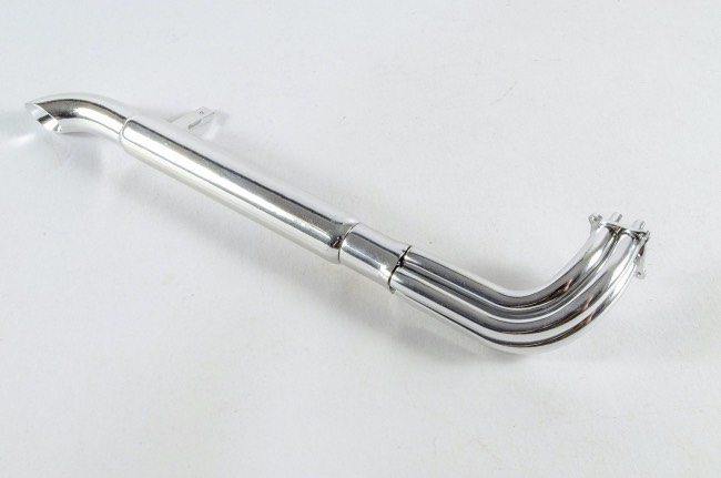 That's it until next time 😊
|
|
|
Rank: Semi-Pro Level 2 Groups: Registered
Joined: 11/01/2017 Posts: 89 Points: 259 Location: Lancashire, UK
|
Pack 2It doesn't seem two minutes since Pack 1, and this beauty rocked up, so it'd be rude not to crack on and build it. Seems strange to be building the engine on this one so early when it was much later with the Shelby Super Snake. Certainly not complaining as I like the detail stuff. STAGE 07: ASSEMBLING THE ALTERNATOR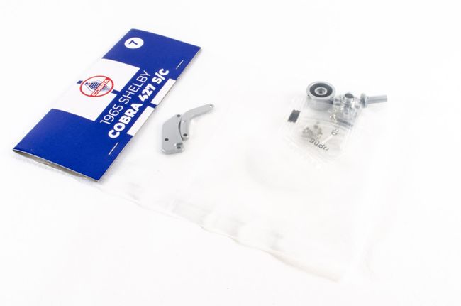 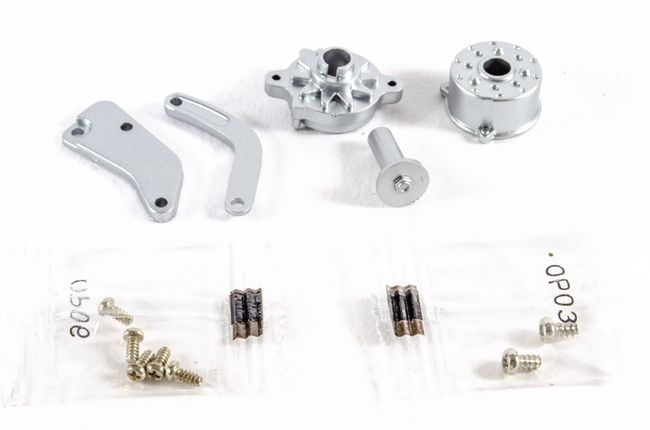 First, the alternator is assembled and then connected to the mounting arm and mounting plate. These last parts are then swung around, pushed together and then mounted to the oil filter assembly that was built in the last pack. 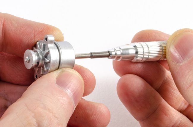 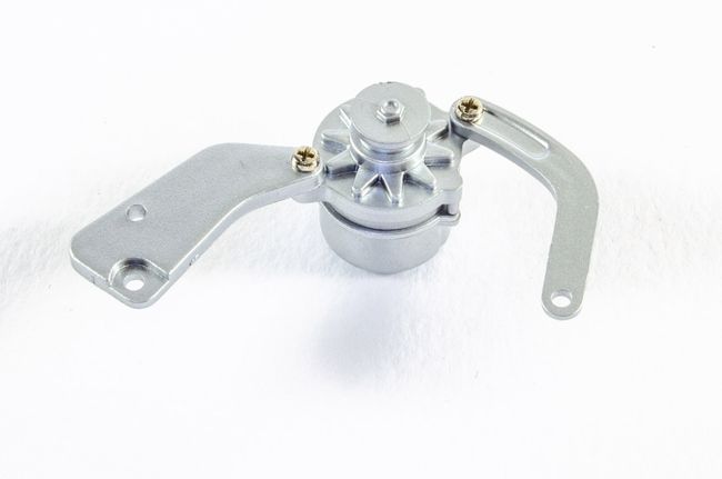 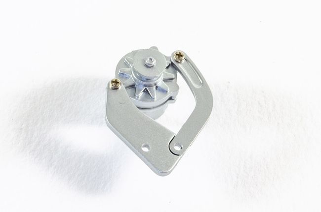 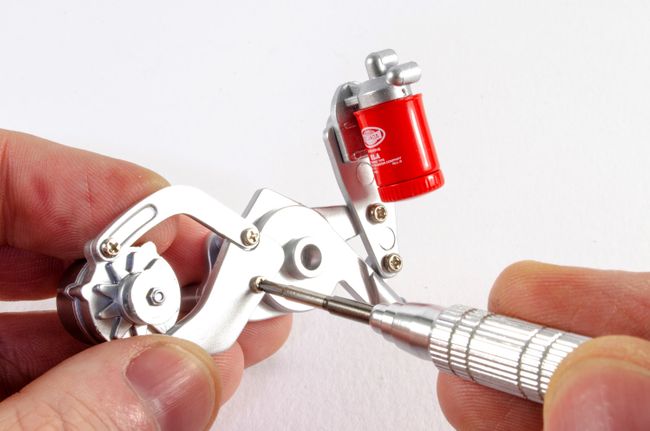 STAGE 08: WATER PUMP PULLEY, CRANK SHAFT PULLEY AND TIMING BELT COVER STAGE 08: WATER PUMP PULLEY, CRANK SHAFT PULLEY AND TIMING BELT COVER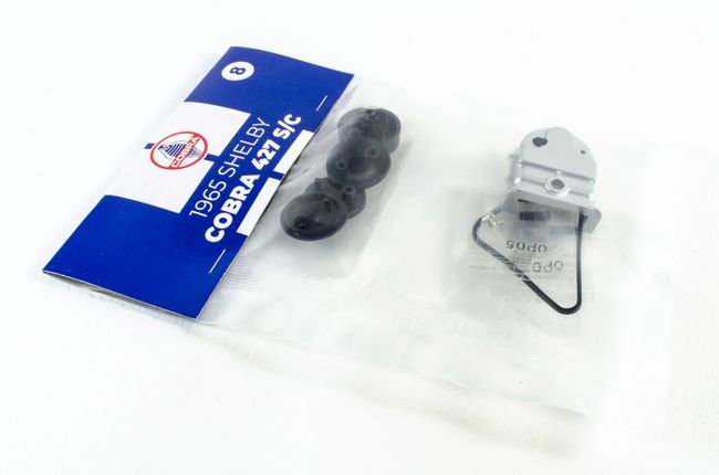 Work carries on with this part of the engine as the crank shaft and water pump pulleys are screwed together. The timing belt cover is then attached and timing belt added. 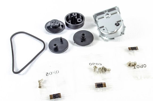 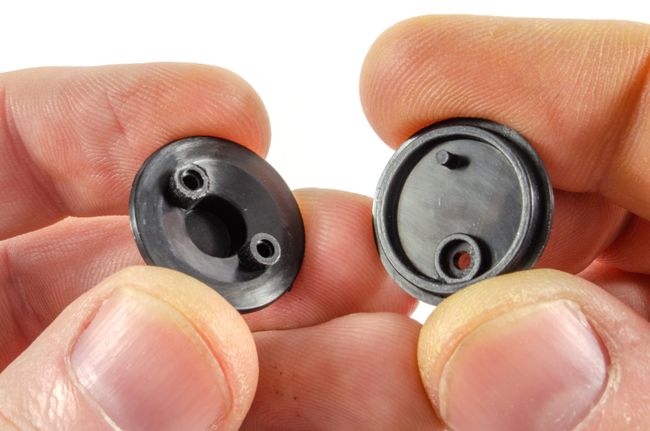 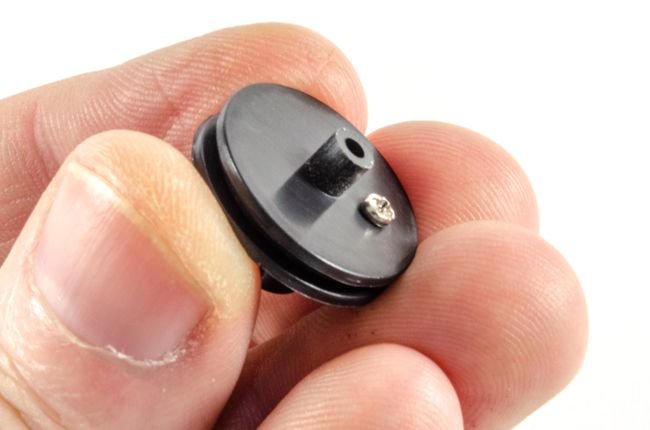 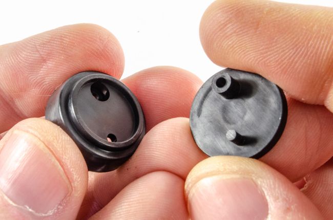 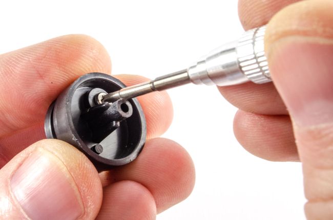 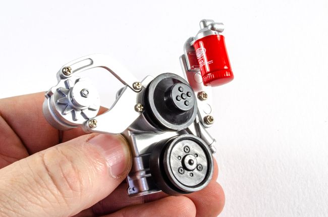 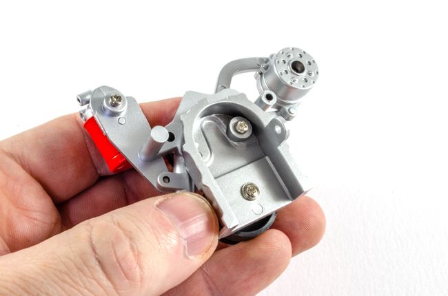 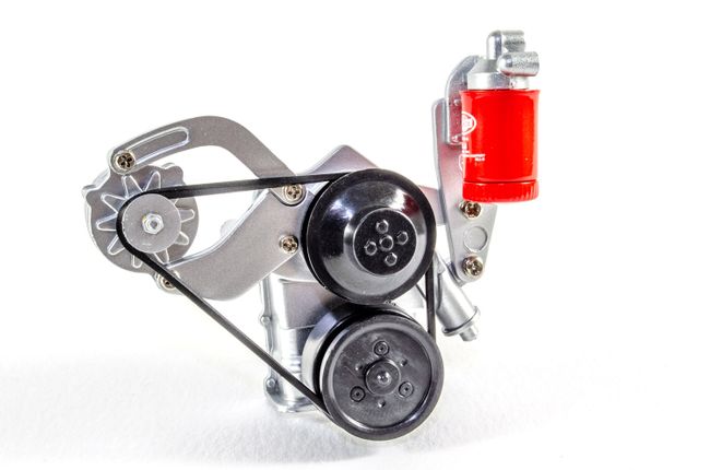 STAGE 09: LEFT CYLINDER HEAD COVER AND EXHAUST MANIFOLD PIPES STAGE 09: LEFT CYLINDER HEAD COVER AND EXHAUST MANIFOLD PIPES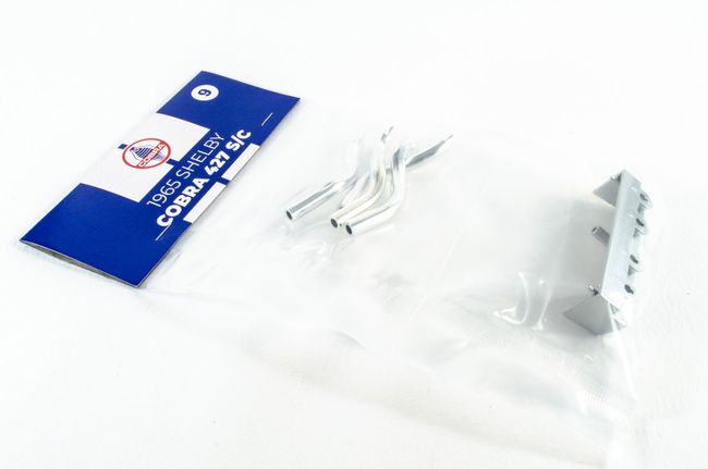 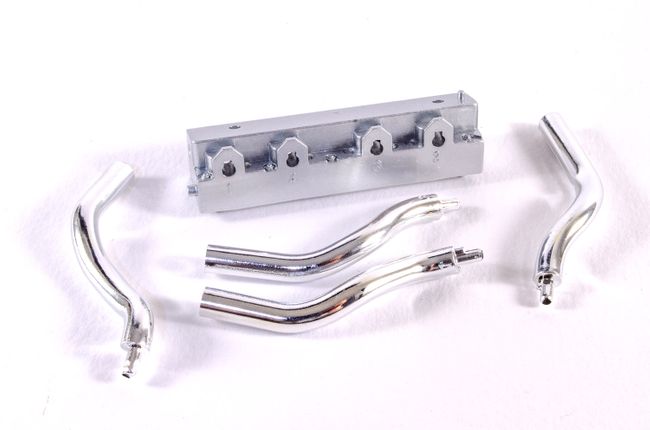 This pack only takes a minute or two to complete. All the manifold parts are numbered, as are the ports on the cylinder head cover. They can only fit one way too as they are keyed. 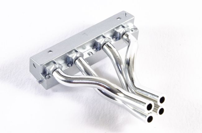 STAGE 10: RIGHT CYLINDER HEAD COVER AND EXHAUST MANIFOLD PIPES STAGE 10: RIGHT CYLINDER HEAD COVER AND EXHAUST MANIFOLD PIPES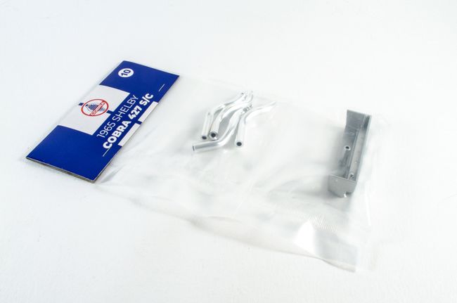 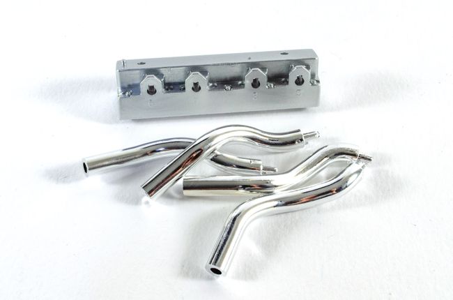 ...just the same for this pack, and then both cylinder head blocks can be tarted up with stage 11. STAGE 11: ROCKER COVERS, CAPS AND SPARK WIRE HOLDERS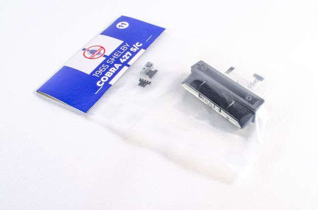 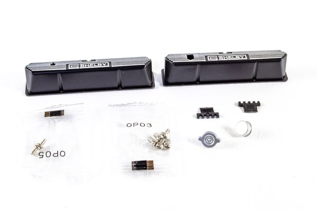 Both rocker cover caps are fitted to the rocker covers and these are in turn screwed to the cylinder head blocks. The spark plug wire holders are a little tricky. They kept dropping off my engine, but were later fixed using a knife and a spot of CA. 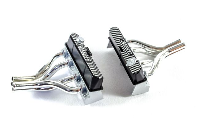 STAGE 12: DISTRIBUTOR, FUEL FILTER, IGNITION COIL AND CYLINDER HEAD CAP STAGE 12: DISTRIBUTOR, FUEL FILTER, IGNITION COIL AND CYLINDER HEAD CAP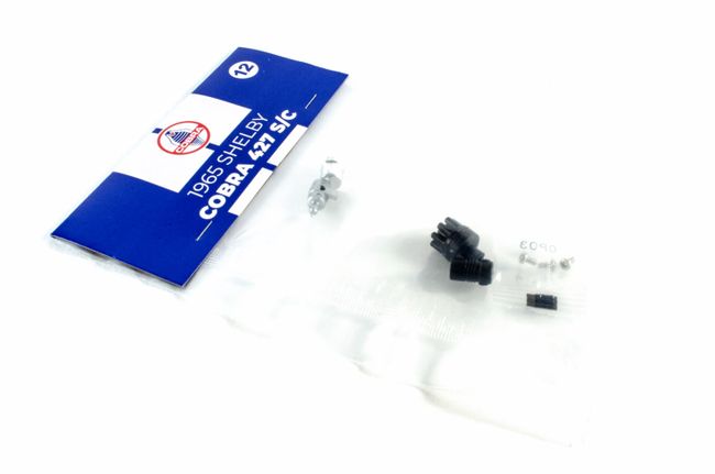 The ignition distributor and fuel filter are fastened to the upper engine block with a single screw each.  The Cylinder Head Central Cover cap and ignition coil are then friction-fitted to the cylinder blocks. 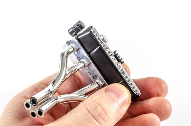  STAGE 13: ENGINE BLOCKS AND COOLING FLUID TANK BRACKET STAGE 13: ENGINE BLOCKS AND COOLING FLUID TANK BRACKET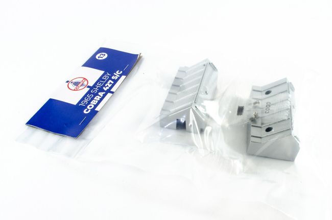 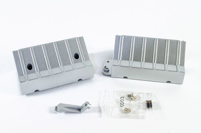 Not a fan of heavy metal, but it's definitely appreciated in a build like this. With these parts, I can start to see how things will finally come together. The right ending block is screwed to the right cylinder head assembly. 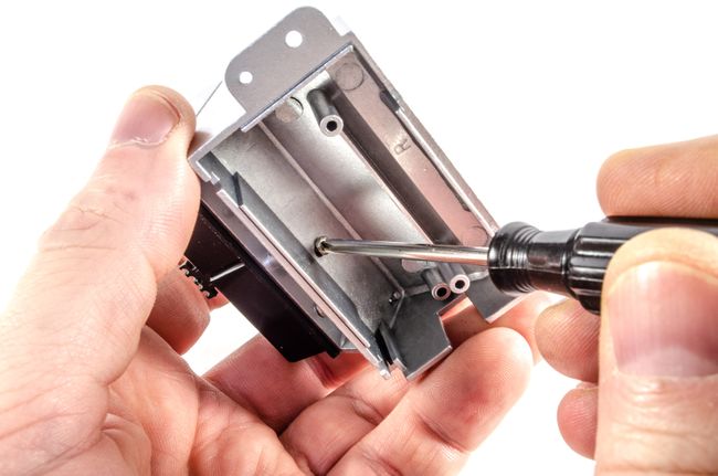 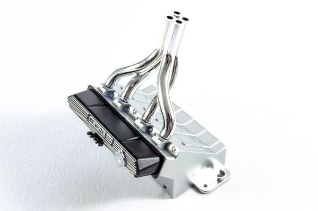 The same applies to the left hand engine block and cylinder head assembly. 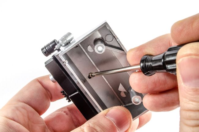 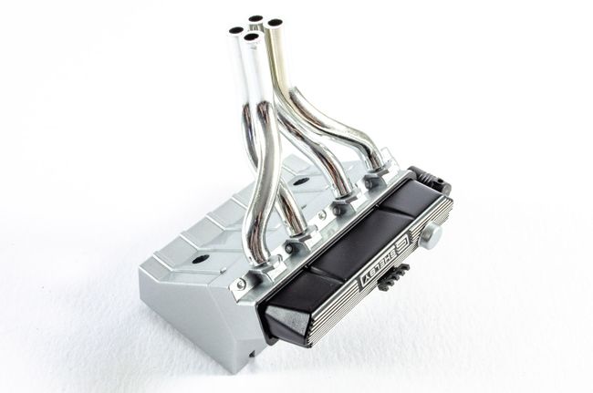 STAGE 14: FLYWHEEL COVER, GEARBOX, INSPECTION COVER, GEARBOX RODS STAGE 14: FLYWHEEL COVER, GEARBOX, INSPECTION COVER, GEARBOX RODS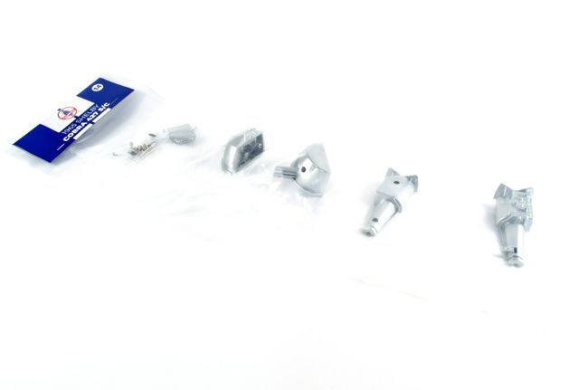 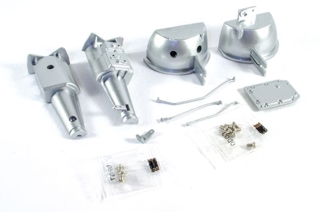 Screws are fitted to the reverse of the gearbox inspection hatch. 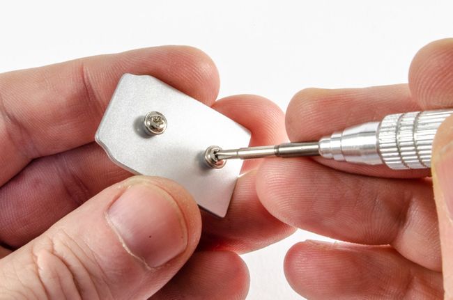 The right flywheel cover is then fitted to the right hand engine block... 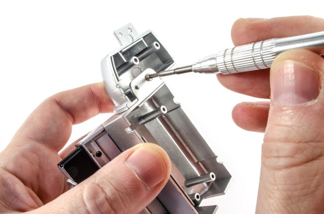 ...followed by the left hand flywheel cover and right hand side of the gear box. 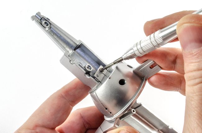 After sliding the inspection hatch into position, the other half of the gearbox is screwed into position. 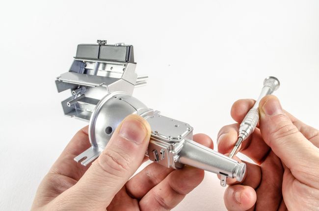 All three gearbox rods are now installed. 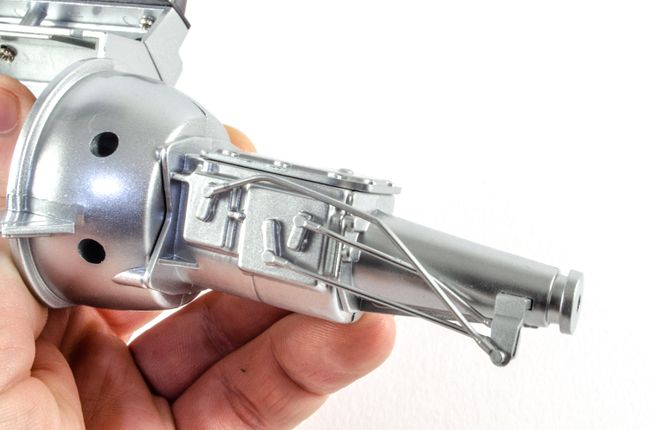 STAGE 15: OIL PAN, PROTECTIVE PLATE, SPARK PLUGS, SPARK PLUG WIRE AND WIRE CONNECTORS STAGE 15: OIL PAN, PROTECTIVE PLATE, SPARK PLUGS, SPARK PLUG WIRE AND WIRE CONNECTORS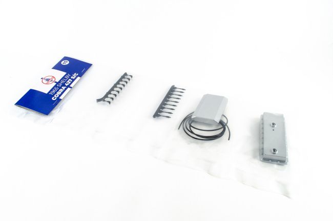 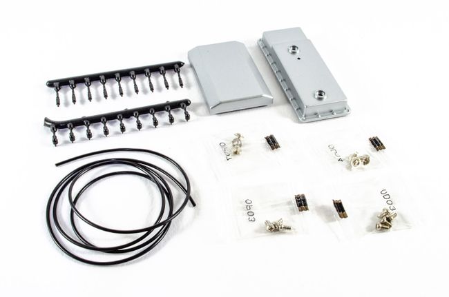 The oil pan is screwed to the protective plate. 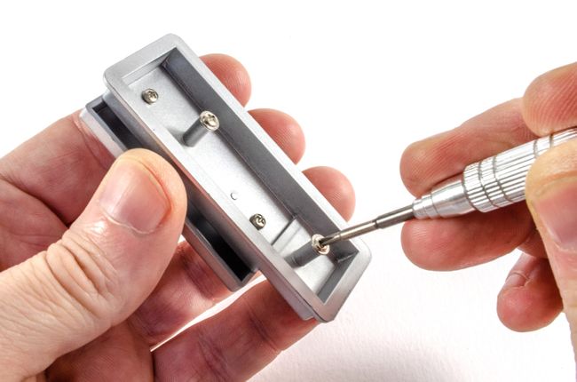 This model utilises a lot of hidden connections like this where screws are fastened on the inside and the flanged head is trapped between other assemblies. A neat trick to minimise external screw holes. 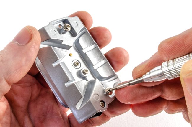 The timing belt assembly is now slotted into position the right hand engine block... 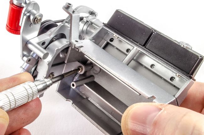 ...and the protective plate fitted. 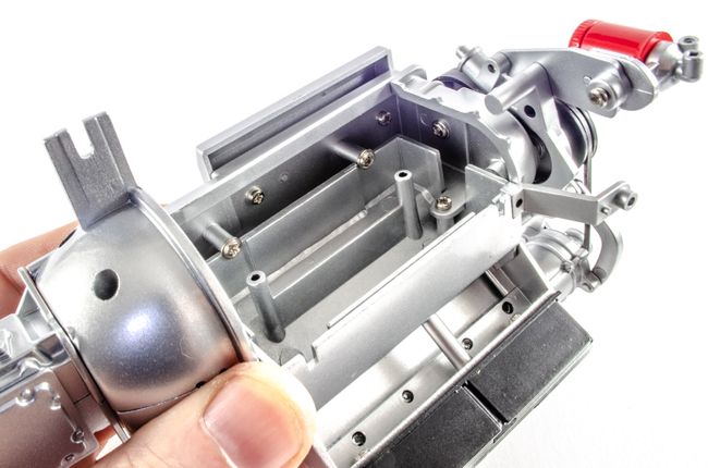 The top of the engine is now fitted into position. 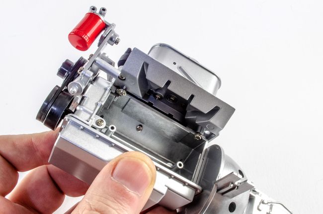 Both sides of the engine block area finally brought together, trapping the other sub assemblies, and creating a large and heavy engine. 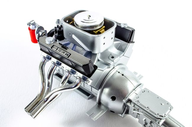 Care is needed to attach the spark plugs. A little push and they click into place. There is some wobble in them, but nothing I'm particularly bothered about. 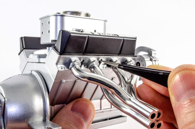 And then the ignition lines are fitted. using a colour coded guide (for cutting the vinyl hose) and also for orientation of the leads to the ignition distributor.  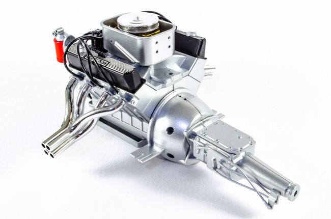 More soon!
|
|
|
|
|
Great job on a nice looking kit James.
Malc.
|
|
|
Rank: Semi-Pro Level 2 Groups: Registered
Joined: 11/01/2017 Posts: 89 Points: 259 Location: Lancashire, UK
|
RM1 wrote:Great job on a nice looking kit James.
Malc. Cheers Malc, Loving it, right down to the working hood latches!
|
|
|
Rank: Semi-Pro Level 2 Groups: Registered
Joined: 11/01/2017 Posts: 89 Points: 259 Location: Lancashire, UK
|
Pack 3This pack now means that we're already a quarter way through this beautiful car model. Even though I absolutely love the Super Snake, I feel this one is even nicer, with its all metal chassis and ingenious assembly. You really do get the feeling that you're actually creating some engineering. Everything fits just perfectly in every way, and she's already gaining some early weight 😆 Ok, let's crack on! STAGE 16: LEFT LATERAL CHASSIS MAIN FRAME BOTTOM SECTION Cross-members 3 & 4 bottom section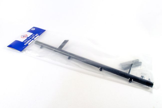 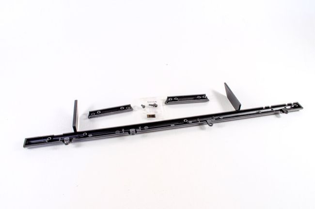 The left lateral chassis bottom frame is the main player here, and all we need to do is to fasten the two bottom halves of the cross members 3 and 4 to the frame. These are clearly numbered and there's nothing to go wrong here. 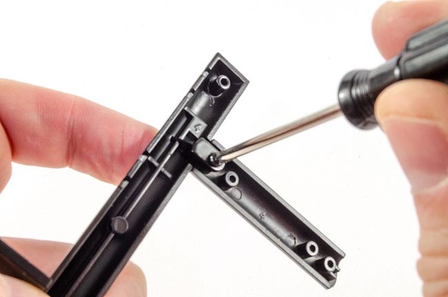 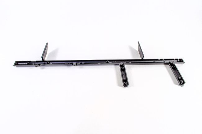 STAGE 17: RIGHT LATERAL CHASSIS MAIN FRAME BOTTOM SECTION Cross-members 1 & 2 bottom section STAGE 17: RIGHT LATERAL CHASSIS MAIN FRAME BOTTOM SECTION Cross-members 1 & 2 bottom section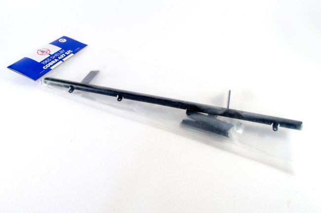 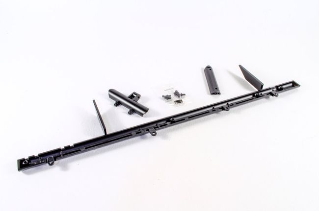 Now it's the turn of the right lateral chassis bottom frame. The cross members first screw to the left hand frame that I just built, taking care to get the offset holes in No.2 bottom cross member, facing the front of the chassis. With these in place, the new right hand frame section can be screwed to the left hand side, creating a symmetrical unit. 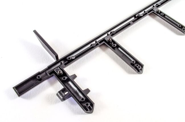 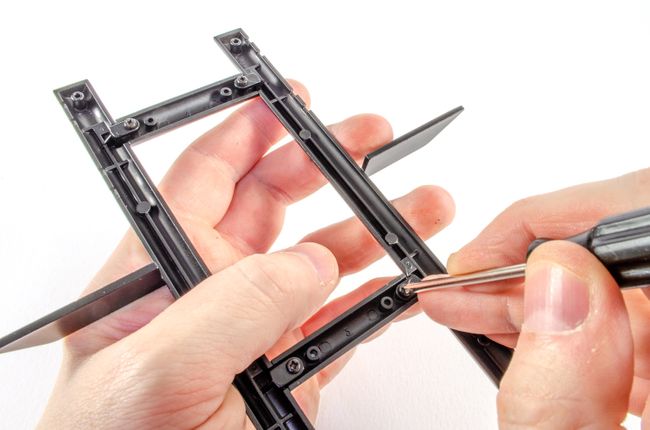 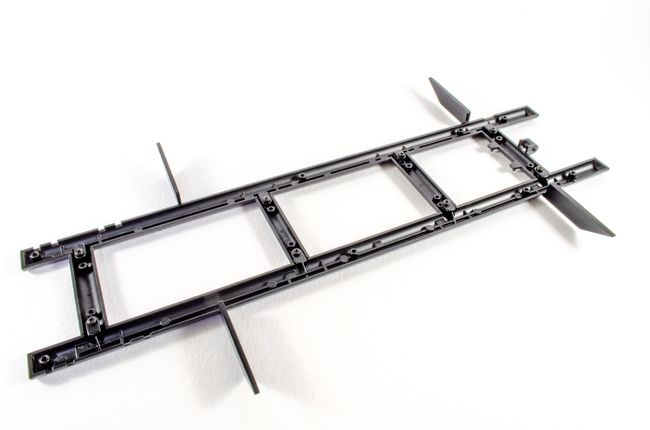 STAGE 18: FRONT SUSPENSION SUPPORT: Cross-member No. 4 Top, Left Horn, Right Horn STAGE 18: FRONT SUSPENSION SUPPORT: Cross-member No. 4 Top, Left Horn, Right Horn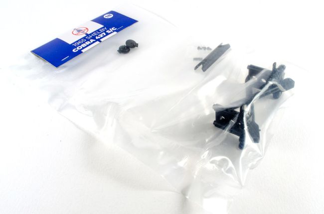 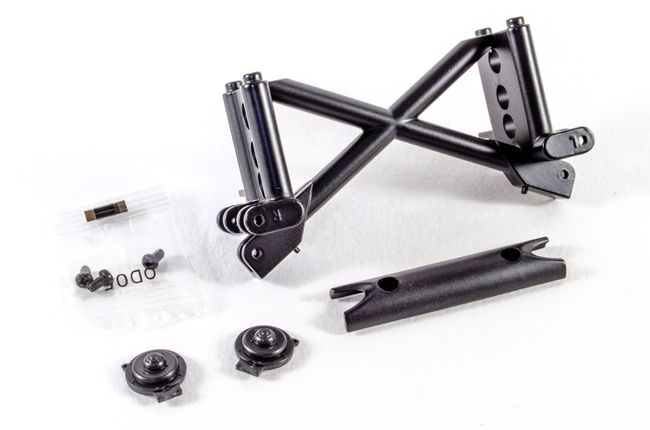 The first part to fit to the lower/bottom frame is the upper part of cross member No.4. 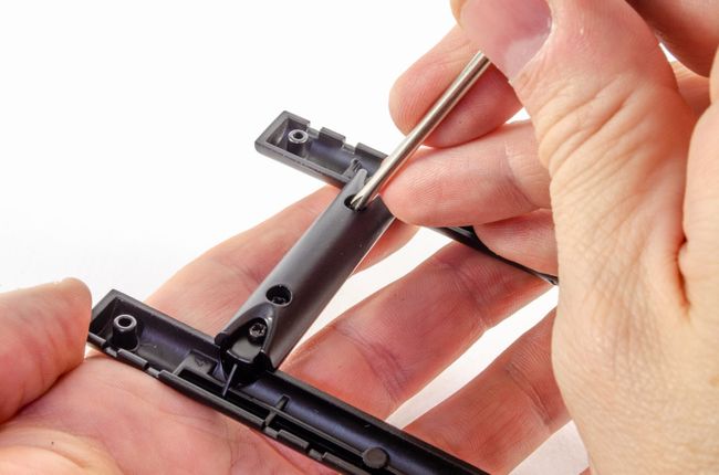 The left and right horns now push onto the front suspension support. No glue needed here. This is now put aside until the next stage. 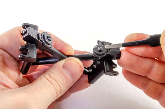 STAGE 19: LEFT LATERAL CHASSIS MAIN FRAME TOP SECTION STAGE 19: LEFT LATERAL CHASSIS MAIN FRAME TOP SECTION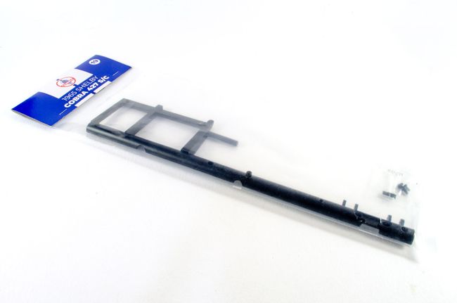 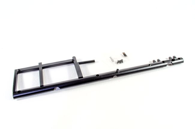 Yet more frame work! The front suspension support from the last stage is now screwed to the lateral left top chassis in this new packet. For this stage, that's it. 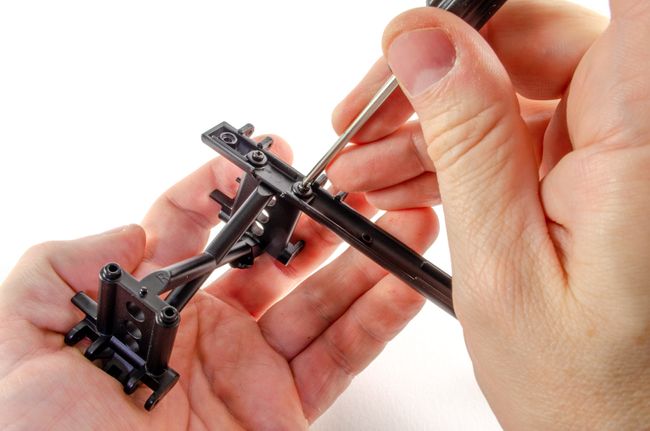 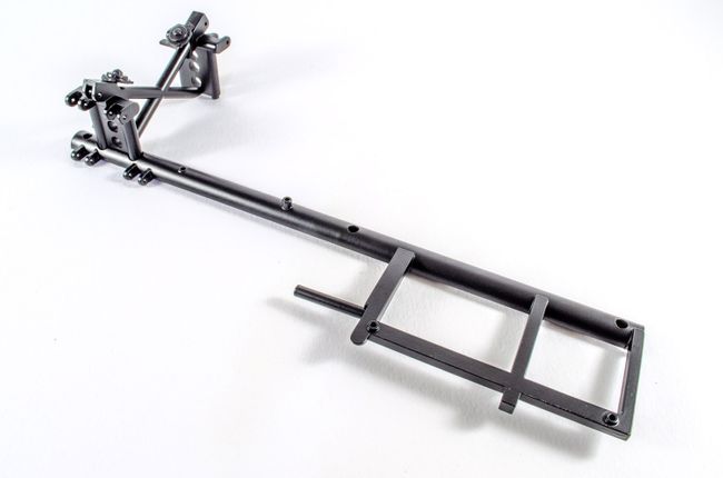 STAGE 20: RIGHT LATERAL CHASSIS MAIN FRAME TOP SECTION Cross-members 2 & 3 bottom top section STAGE 20: RIGHT LATERAL CHASSIS MAIN FRAME TOP SECTION Cross-members 2 & 3 bottom top section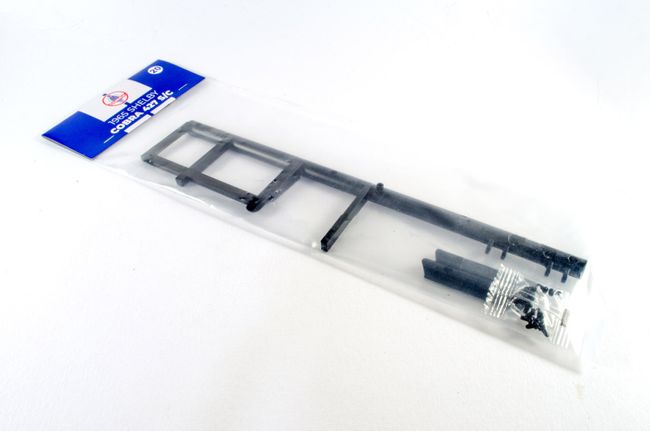 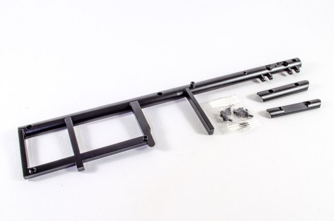 Now the right top lateral chassis can be screwed to the previous assembly as shown. 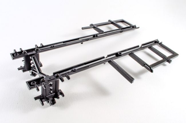 You can see just how well everything fits together as the top frame is fastened to the lower frame. Six screws hold these firmly in place. 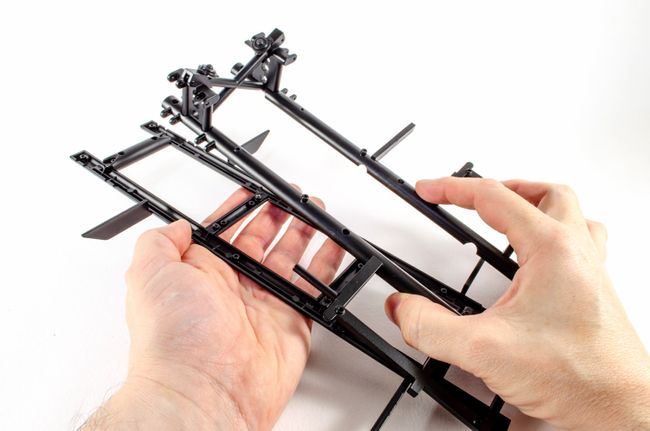 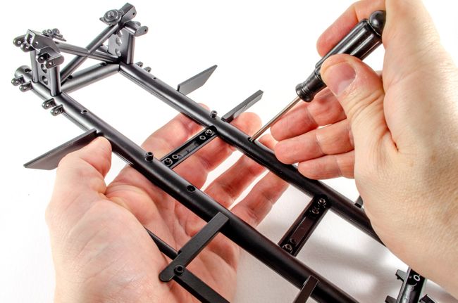 Lastly, the two remaining upper cross member parts (No.1 and 2) are screwed into position. Again, numbers are cast into the parts so you really can't get this wrong. 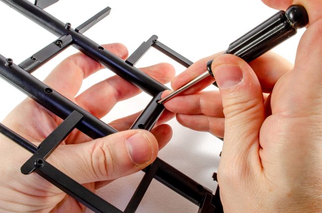 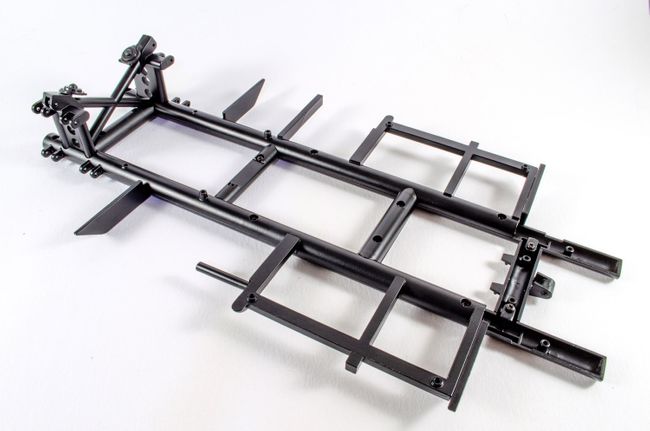 STAGE 21: REAR CHASSIS PART & WISHBONE MOUNTING STAGE 21: REAR CHASSIS PART & WISHBONE MOUNTING 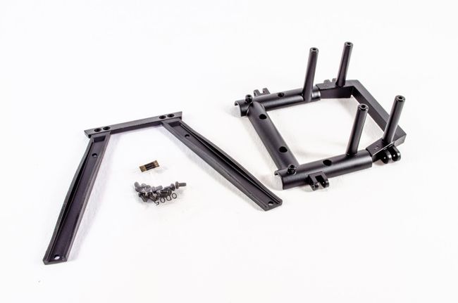 The rear chassis is first screwed into position... 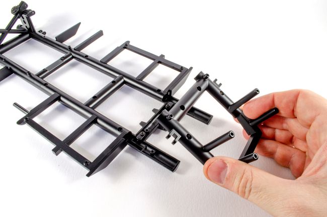 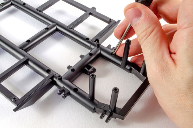 ...followed by the rear suspension wishbone mounting frame. 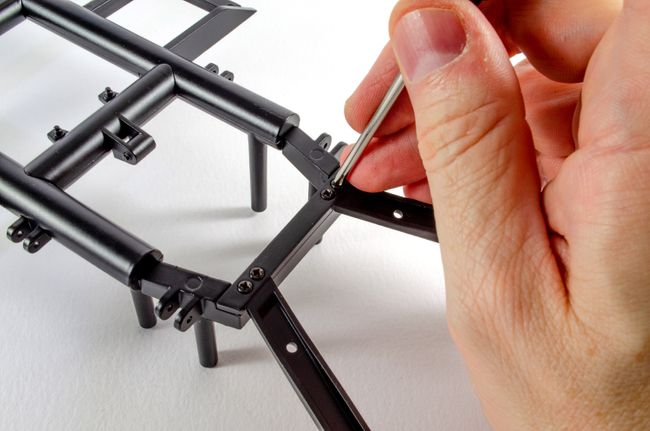 Definitely some weight here now! Remember, this is all metal. 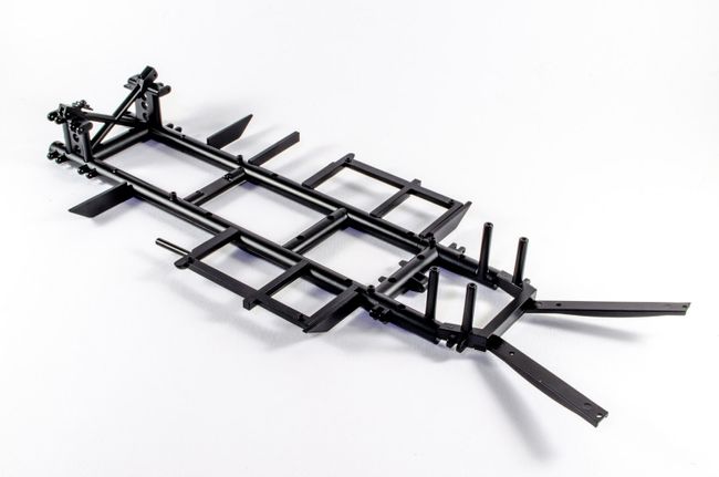 STAGE 22: RIGHT FRONT INNER & OUTER WHEEL RIM STAGE 22: RIGHT FRONT INNER & OUTER WHEEL RIM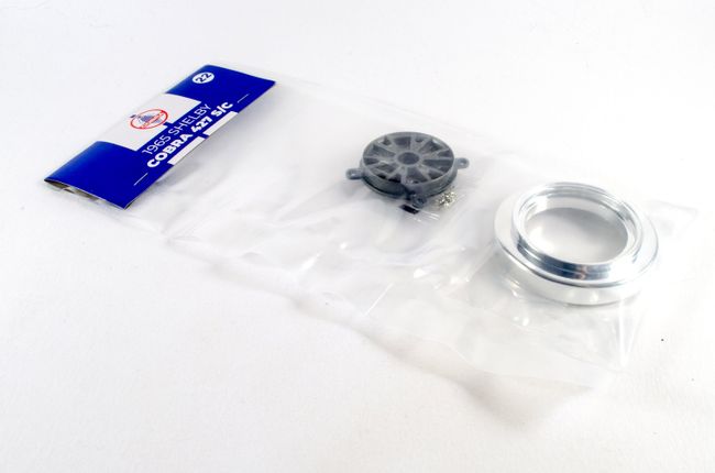 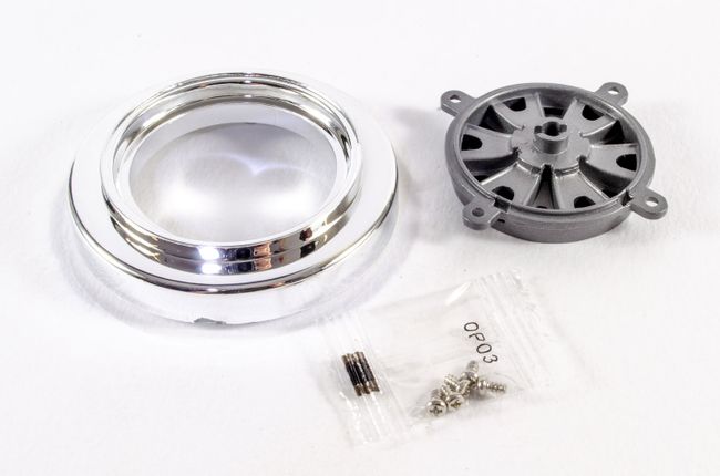 The front inner and outer rims are screwed together. A very simple stage. 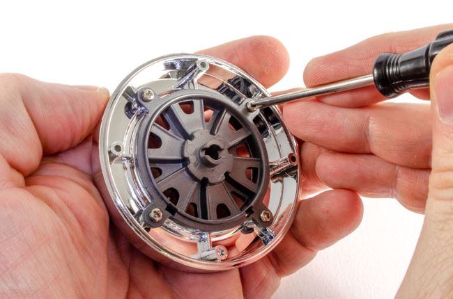 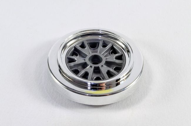 STAGE 23: TIRE & OUTER RIM STAGE 23: TIRE & OUTER RIM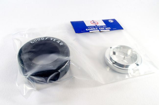 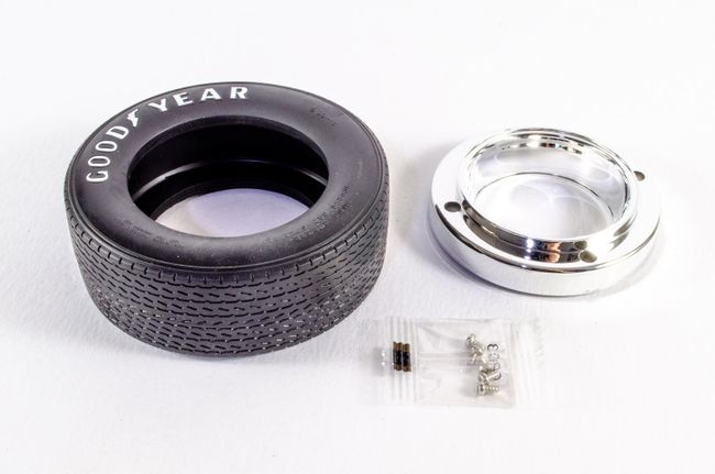 The reverse of this wheel is now screwed into position and the tyre added. To get the tyre on, it really does need to be soaked in freshly boiled water for about 5 minutes to make it pliable. Without that, you will most certainly struggle. 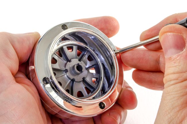 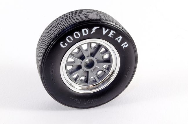 ...more next time!
|
|
|
Rank: Semi-Pro Level 2 Groups: Registered
Joined: 11/01/2017 Posts: 89 Points: 259 Location: Lancashire, UK
|
Pack 4
STAGE 24: BRAKE PARTS FOR THE FRONT RIGHT WHEEL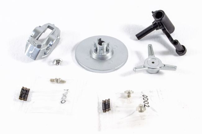 In this stage, we simply build the brake unit for there front wheel. To start with, the spinner and hubcap are first pushed together. No glue needed here. 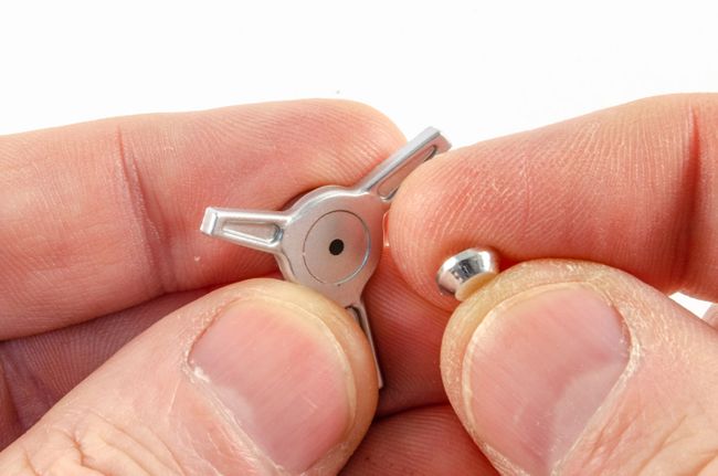 The wheel hub now inserts through the brake disc so that it freely rotates. The brake calliper then screws to the wheel hub whilst entrapping the brake disc. 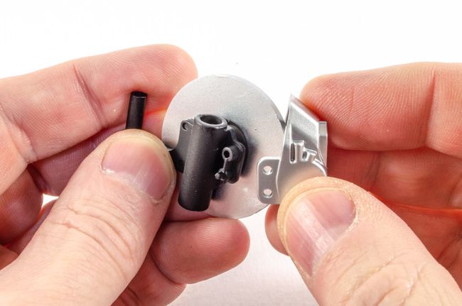 The brake unit can now be fitted to the right wheel. This will only go in one way, and then a screw from the outside holds the two together. The spinner/hubcap them sits over the screw using its magnet. 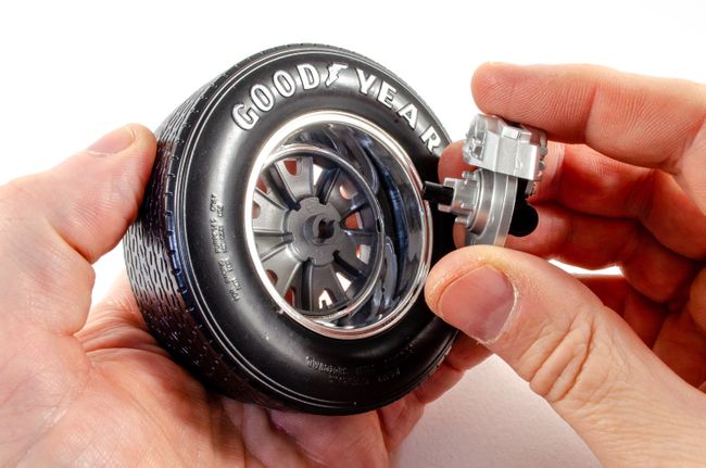 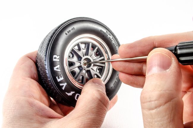 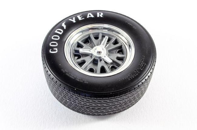 STAGE 25: LEFT AND RIGHT FLOOR PANELS STAGE 25: LEFT AND RIGHT FLOOR PANELS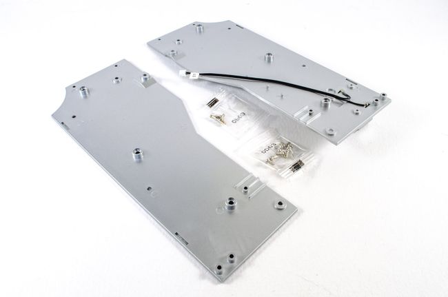 Before any work starts here, it's a good idea to use a bit of tape to hold the battery box line down on the part. I saw this on a build on the Agora forum, and it's a great idea! 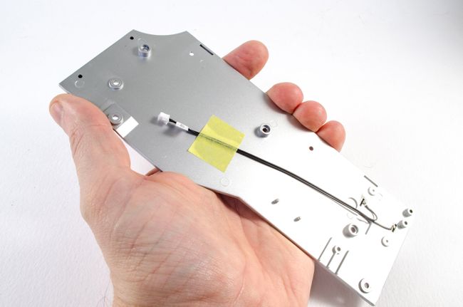 The two floor panels are now screwed to the chassis with 4 screws each. The fit is perfect. 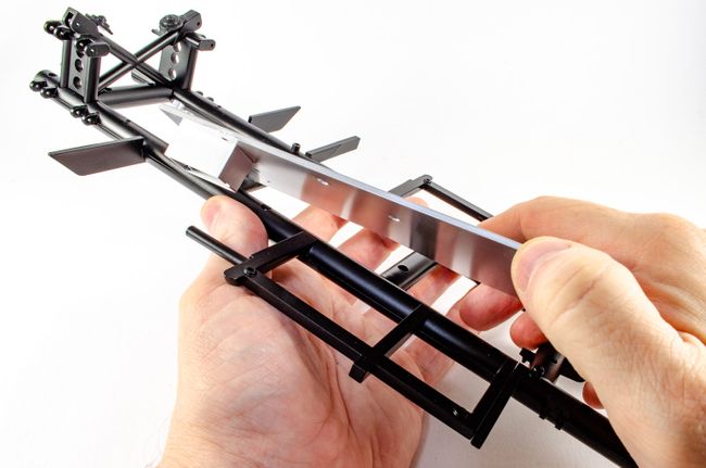 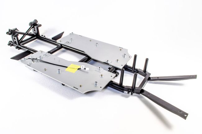 And now the good bit...the engine is installed! Just two screws for this. I also took the opportunity to tidy up the cables a little as I left it a real mess last time. 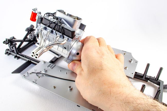 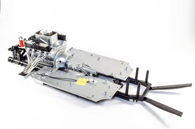 STAGE 26: BRAKE PARTS FOR THE REAR LEFT WHEEL STAGE 26: BRAKE PARTS FOR THE REAR LEFT WHEEL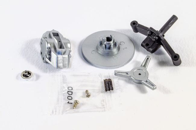 As with the right brake unit, the left one is now built. Oddly enough, the wheel hub is shown as silver in the manual, but this is a nice black coated metal part. 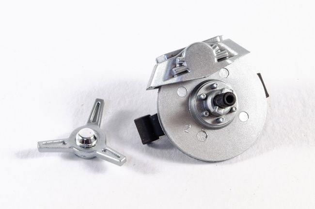 STAGE 27: DIFFERENTIAL HOUSING COMPONENTS STAGE 27: DIFFERENTIAL HOUSING COMPONENTS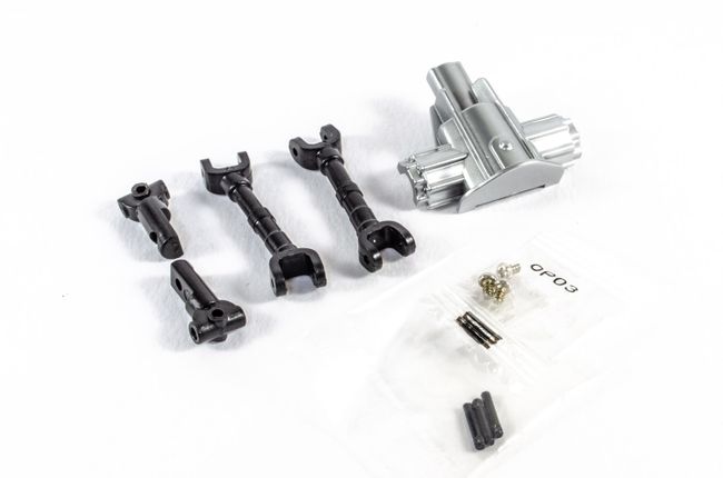 The inboard drive shaft connectors are screwed to the bottom of the differential housing. 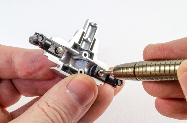 Both drive shafts are now fitted and held in position with a serrated tipped pin. The drive shafts are labelled L and R to make sure they go on the correct sides. This is important due to the various offsets in each part. 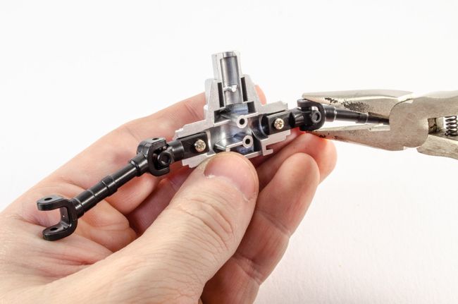 The left rear wheel brake unit is now pinned into position pin the same way. 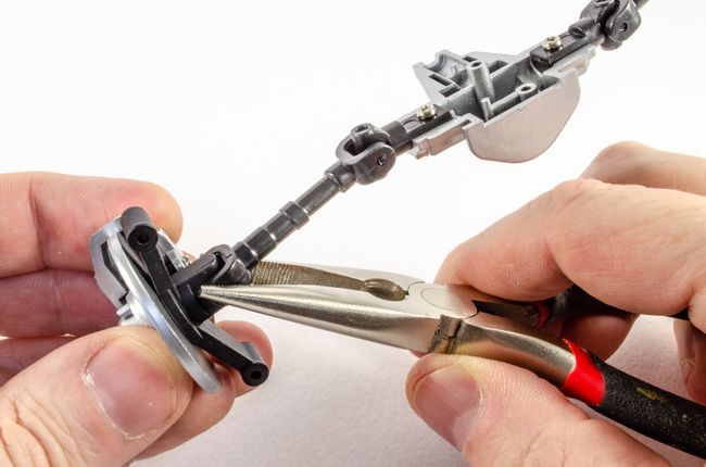 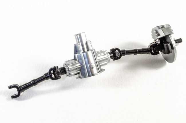 STAGE 28: DIFFERENTIAL HOUSING COMPONENTS AND PROPELLER SHAFT STAGE 28: DIFFERENTIAL HOUSING COMPONENTS AND PROPELLER SHAFT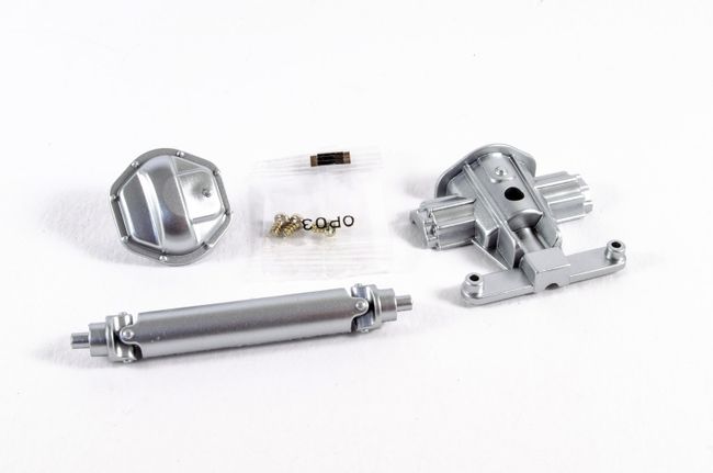 The rear differential housing cover pushes into housing unit, and then the top of the housing unit is screwed into position. 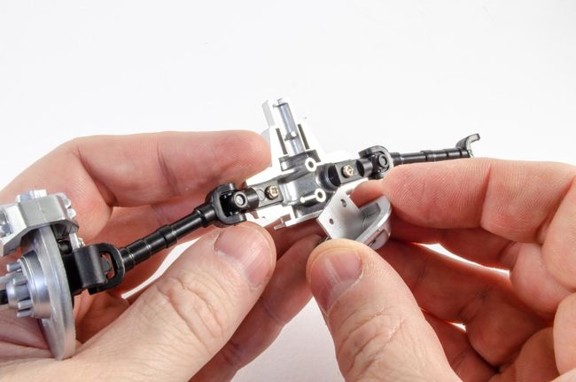 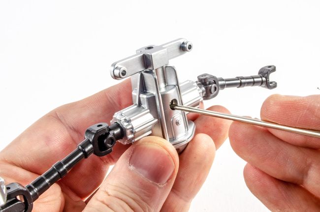 The propeller shaft is carried over onto the next stage. 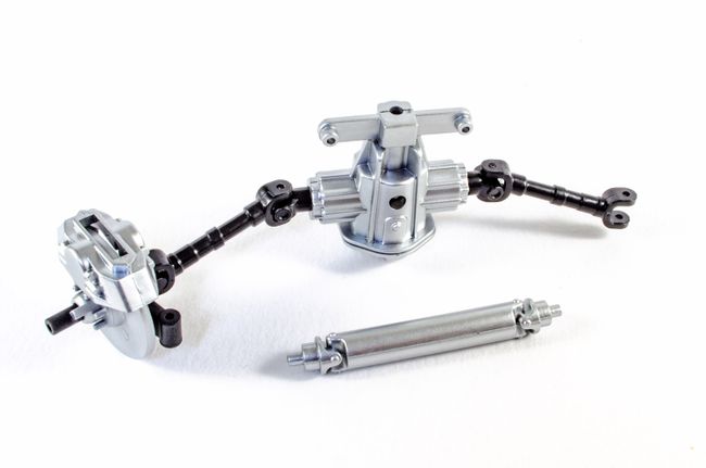 STAGE 29: REAR UPPER SUSPENSION ARMS STAGE 29: REAR UPPER SUSPENSION ARMS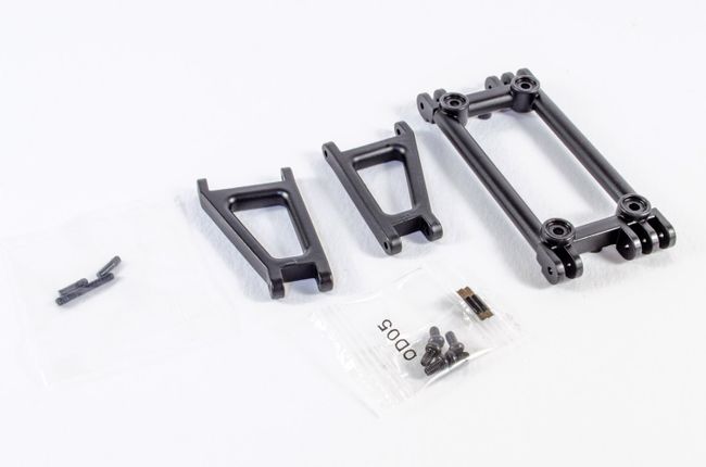 More serrated pins are used to connect the rear upper arms to the arm holder. 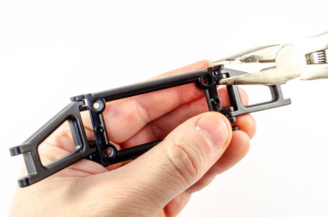 The differential unit is now loosely sat in place and connected to the engine by the propeller shaft. With this is situ, the arm holder is screwed into position, trapping the differential unit, and the arm is connected to the brake unit with another serrated pin. 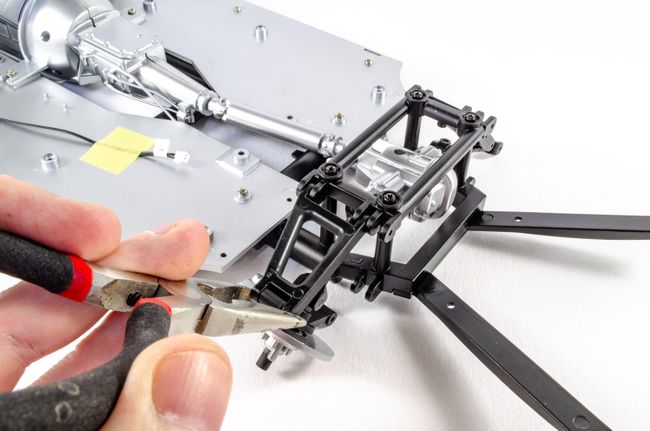 STAGE 30: LEFT LOWER SUSPENSION ARM AND SHOCK ABSORBER STAGE 30: LEFT LOWER SUSPENSION ARM AND SHOCK ABSORBER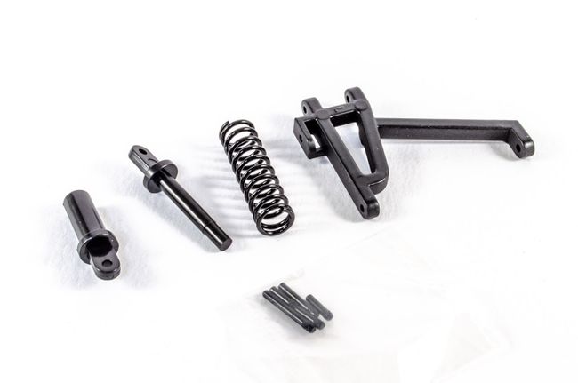 Using another serrated pin, the cylinder body is now fitted into position. 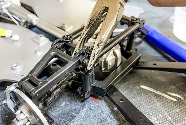 Now, the cylinder piston is connected to the lower arm. With the coil spring in place, this unit is then offered up to the assembly and pinned into position. At this point, there's a lot of tension in this! 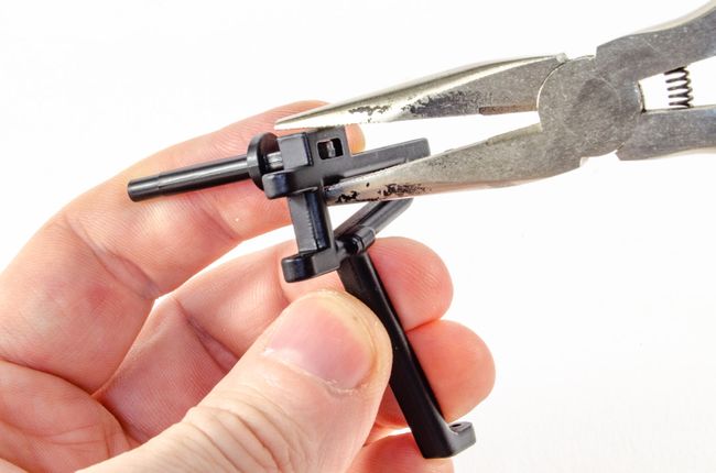 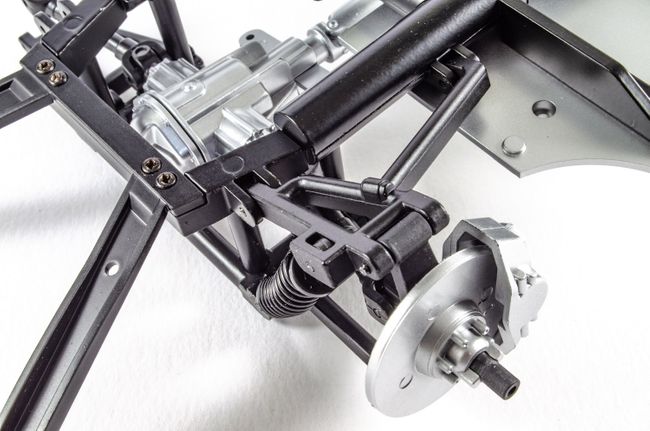 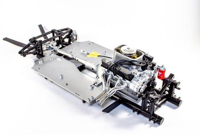 STAGE 31: BRAKE PARTS FOR THE REAR RIGHT WHEEL 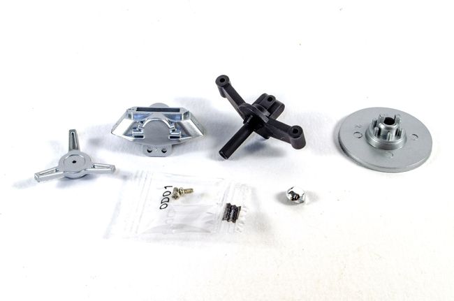 Lastly, another brake unit is built. This time for the rear right wheel. 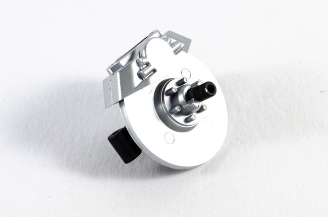 That's it until next time!!
|
|
|
 Rank: Master      Groups: Registered
Joined: 25/11/2018 Posts: 1,284 Points: 3,878 Location: Southeast UK
|
You're making good steady progress with this build James, all very neat and tidy and a very well presented diary too.
Well done, looking good.  
Kev.Per Ardua Ad Astra
|
|
|
 Rank: Super-Elite    Groups: Registered
Joined: 20/10/2016 Posts: 4,504 Points: 13,548 Location: Wiltshire
|
This is going to be a cracking model James. Great work so far!  Regards, Phil W. Completed projects: 1/43 scale Bedford HA van / 1/43 scale MG TD sports car
Current projects: 1/48 scale U-boat [U230]
Future projects: 1/148 scale railway diorama / 1/50 scale R/C Volvo F89 logging truck / 1/148 scale Thunderbirds Fireflash
|
|
|
Rank: Administration  Groups: Administrator, Administrators, Forum Support Team, Global Forum Support, Global Forum Support Team, Moderator, Official Builds Joined: 24/08/2009 Posts: 1,942 Points: 5,838 Location: UK
|
Looking great! I haven’t really got started on mine yet. Too much repainting I want to do, and no cave to do it in yet.
Stay Well!
Mark
|
|
|
Rank: Super-Elite  Groups: Official Builds, Administrators, Moderator, Global Forum Support, Registered Joined: 04/06/2011 Posts: 5,610 Points: 16,982 Location: ipswich
|
Great stuff. I'm looking forward to seeing how this turns out. It looks like a really good kit.
|
|
|
Rank: Semi-Pro Level 2 Groups: Registered
Joined: 11/01/2017 Posts: 89 Points: 259 Location: Lancashire, UK
|
Pack 5I have to say Pack 5 went together very quickly and was a very satisfying project. For me, this one is miles ahead of the beautiful GT500 I'm also building due to all the metal parts and general construction. STAGE 32: REAR RIGHT LOWER CONTROL ARM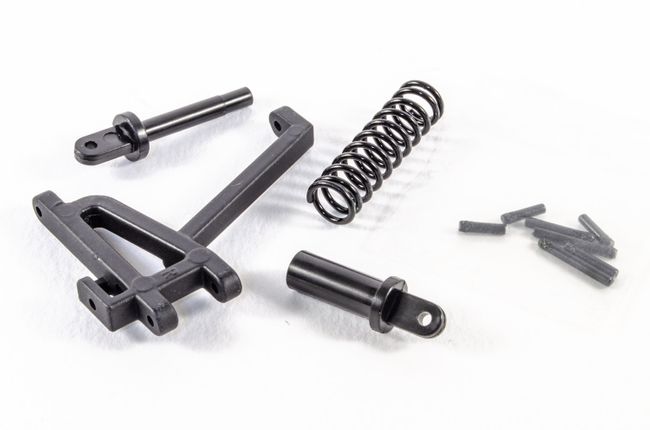 In this stage, we can continue with the suspension stuff that was built in the last pack, and tie some of those literal loose ends up. All of the parts in this are held together with serrated end pins that are pushed home with pointed pliers. The wheel hub built in the last pack can also now be attached. 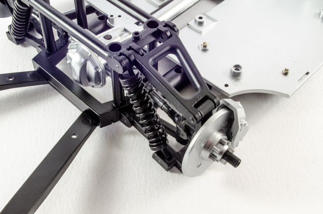 STAGE 33: REAR FLOOR PANEL STAGE 33: REAR FLOOR PANEL The rear floor panel drops into place as shown and is secured by six screws. Two of these secure the floating driveshaft bracket securely in place giving that area some needed rigidity. 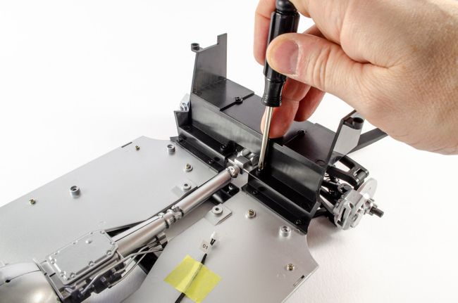 STAGE 34, 35, 37 and 37 (WHEELS!) STAGE 34, 35, 37 and 37 (WHEELS!)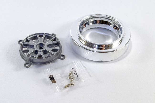 These built up exactly as the front wheels, just four screws per rim. You definitely need to soak those tyres in just-boiled water for 5 mins to make it pliable enough to pull around the rim. The fit is superb! Both rear wheels are built over these stages. 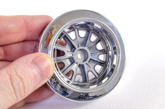 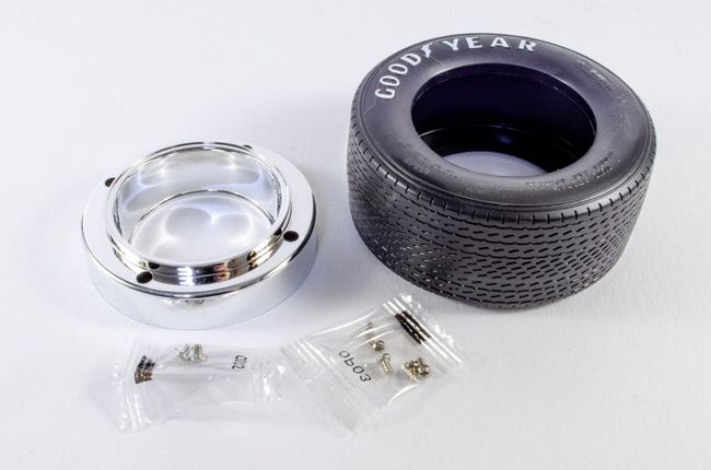 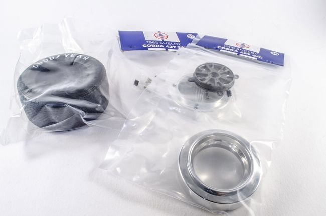 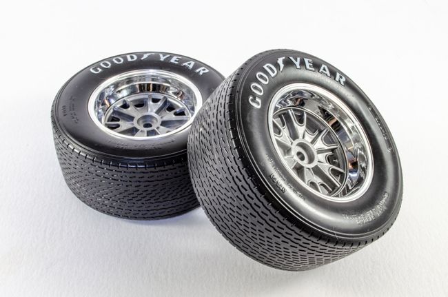 A single screw is now used to fit the wheels to the rear of the car. These were done one after the other so I wasn't putting any stresses on anything for too long. When attaching the wheels, the fins on the brake unit need to fit into the slots in the rear rim. 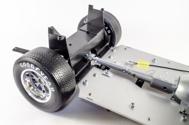 STAGE 38 and 39: FRONT LEFT/RIGHT CONTROL ARMS STAGE 38 and 39: FRONT LEFT/RIGHT CONTROL ARMS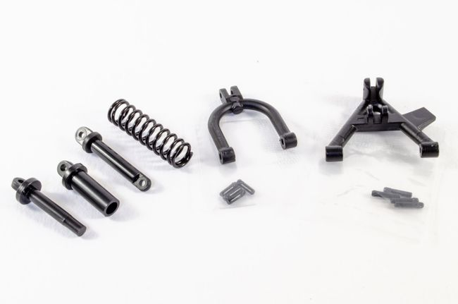 It's now the turn of the front suspension to be completed so the front wheels can be fitted. Again, pins are used throughout to hold everything together while allowing the various joints to move about. 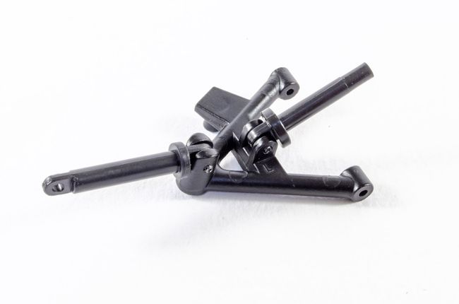 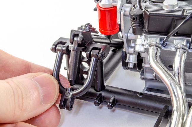 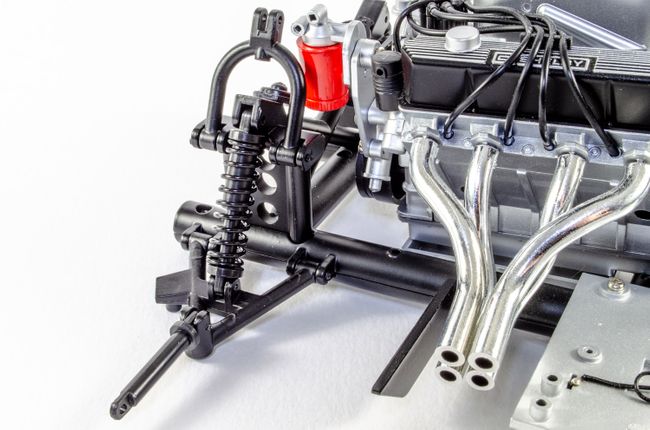 The wheel can now be slipped onto the connecting rod, and then a serrated pin used to lock the rod to the control arm. This was done for both left and right wheels. 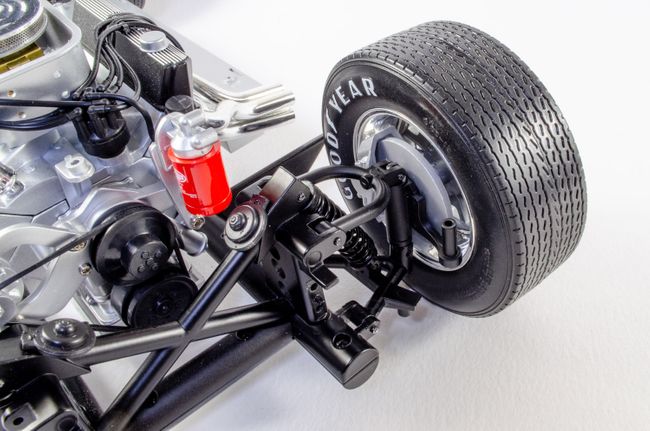 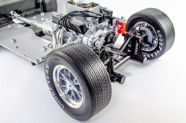 STAGE 40: FRONT FENDER LINERS & AIRFLOW INTAKE PANEL STAGE 40: FRONT FENDER LINERS & AIRFLOW INTAKE PANEL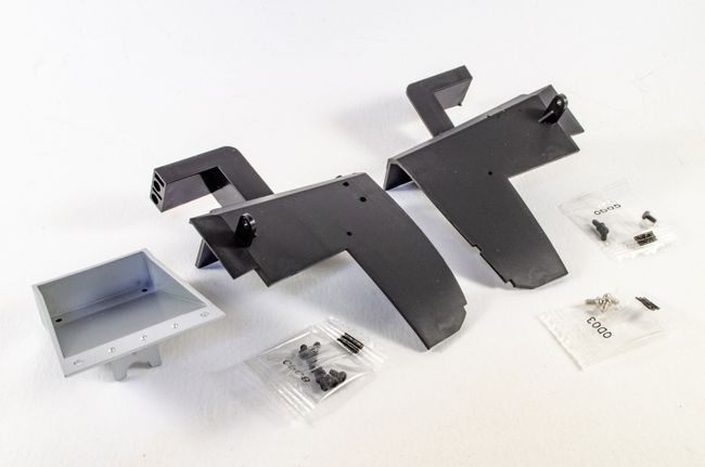 Two screws hold each fender liner to the silver floor base sections, and another screw holds each to the metal chassis making everything very rigid. The car is then flipped over and the airflow intake panel in place before flipping over the correct way and adding two final screws. 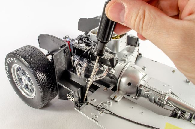 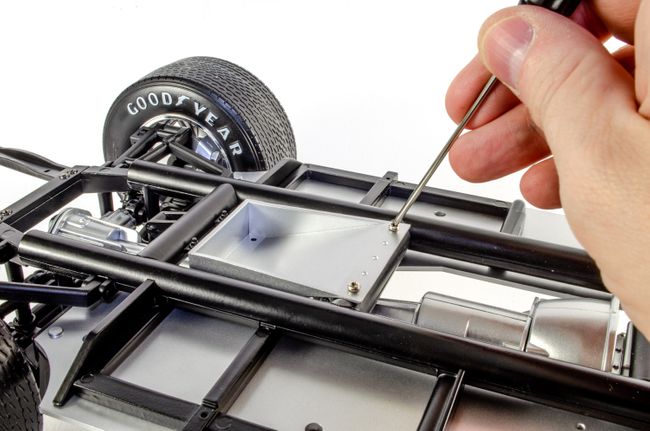 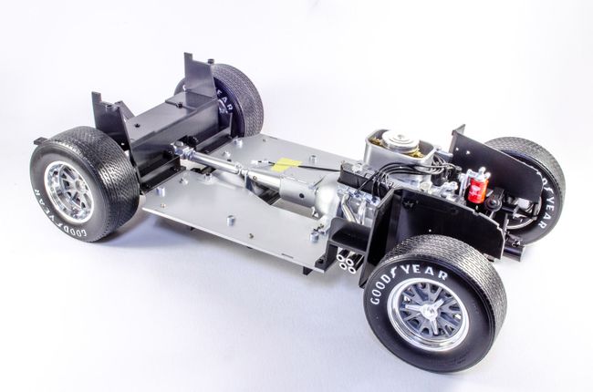 As I have Pack 6, I'll post this real soon, and it looks another wonderful project!
|
|
|
Rank: Master Groups: Registered
Joined: 25/11/2018 Posts: 1,284 Points: 3,878 Location: Southeast UK
|
Excellent work James, all put together very neatly and looking very good. Glad to hear there is a better quantity of metal parts in this kit compared to some earlier offerings. Should give a nice weighty feel to the finished model?
Well done and keep it coming.
Kev.Per Ardua Ad Astra
|
|
|
Rank: Semi-Pro Level 2 Groups: Registered
Joined: 11/01/2017 Posts: 89 Points: 259 Location: Lancashire, UK
|
Kev the Modeller wrote:Excellent work James, all put together very neatly and looking very good. Glad to hear there is a better quantity of metal parts in this kit compared to some earlier offerings. Should give a nice weighty feel to the finished model?
Well done and keep it coming.
Kev. There's defo some weight to it already! Just love the overall quality of this...and here comes the next pack!
|
|
|
Rank: Semi-Pro Level 2 Groups: Registered
Joined: 11/01/2017 Posts: 89 Points: 259 Location: Lancashire, UK
|
Pack 6Hot on the heels of the last pack come this next one which looks at building up some of the driver's office. STAGE 41: DASHBORD SWITCHES AND STEERING ROD GUIDE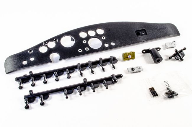 Definitely one for those detail freaks 😁 First, dashboard plates 1 & 2 are pushed into place. I actually used a little CA on #2 as it was a little sloppy. 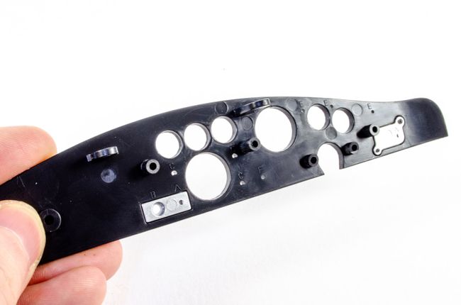 Plate #3 is then pushed into place and secured by a screw from behind. Just look at the detail on that 🤗 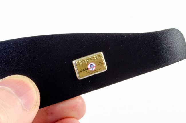 Now, the steering rod guide is screwed into position from the rear, 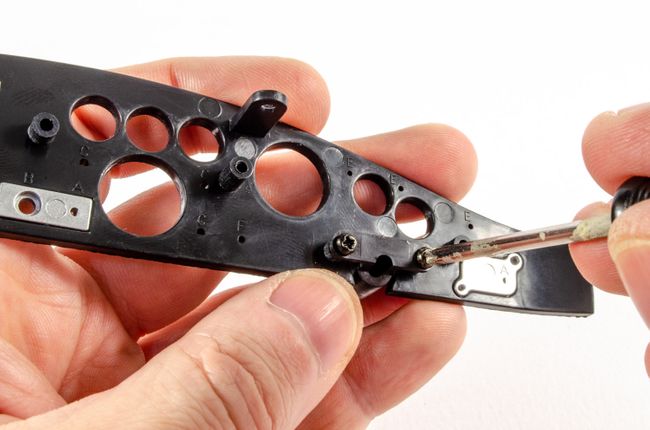 A number of injection moulded switches and knobs are added, some of them printed with details. These look excellent. one of these is quite clearly for a switch as it's left free-floating. 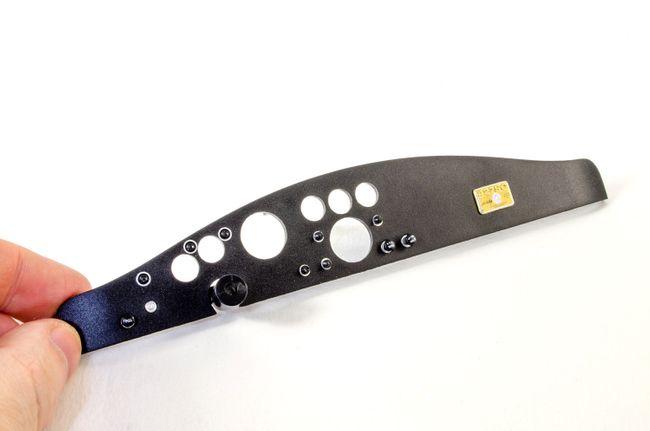 STAGE 42: DASHBOARD DIALS AND SWITCH STAGE 42: DASHBOARD DIALS AND SWITCH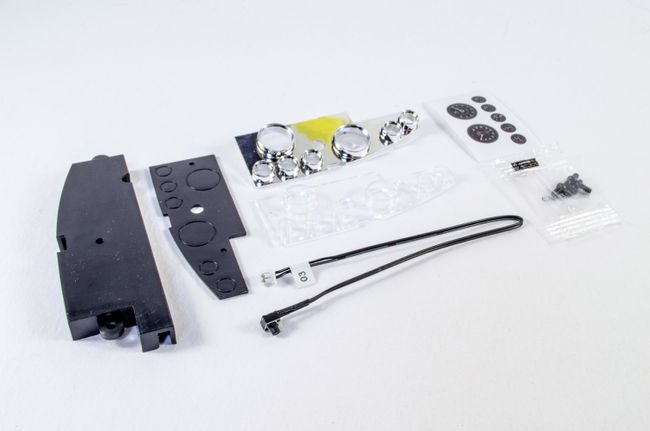 More dashboard goodness now as the dial stickers are affixed to the holding plate. 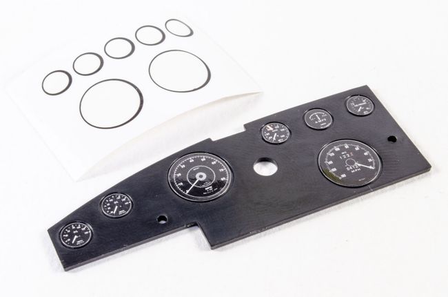 The clear lenses board is now pushed into position on the rear of the chrome surround. 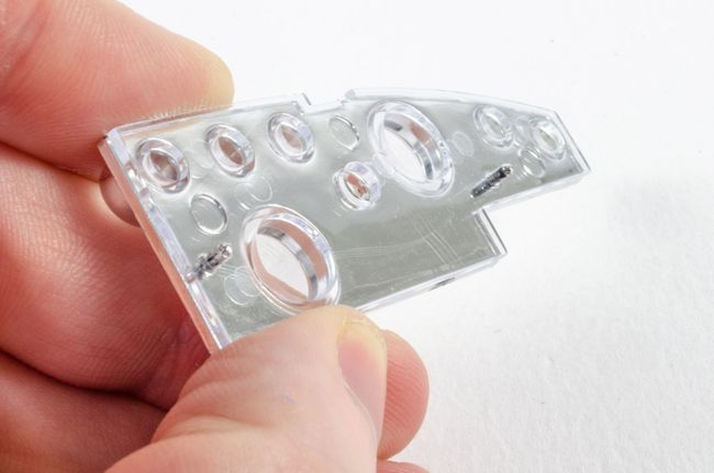 Then the dial faces holder is sat on top of this, behind the lenses board. 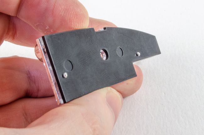 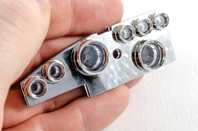 Remember the free-floating switch? This is what it operates. A microswitch is pushed into position in the dial holding plate, and this fitted to the dials assembly I just made, before being fitted to the rear of the instrument panel using three screws. 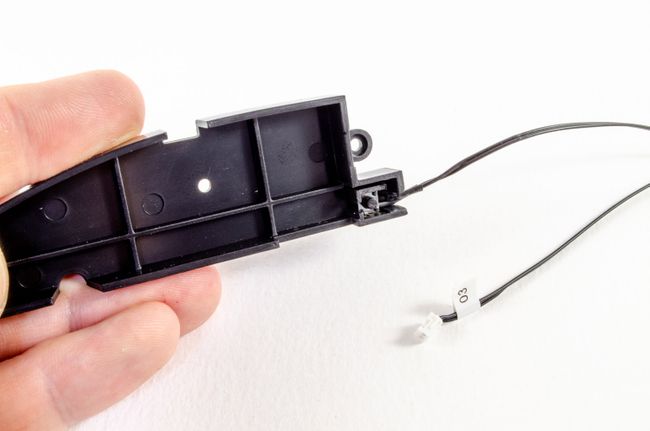 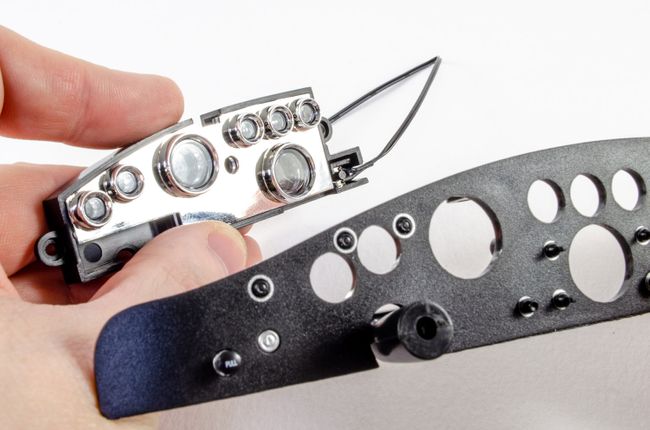 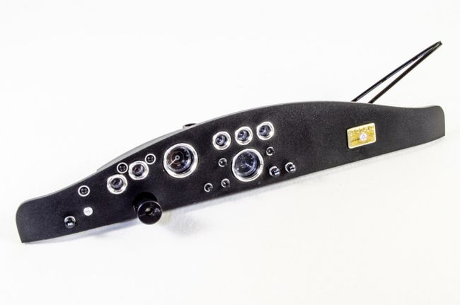 STAGE 43: CENTER CONSOLE AND LEFT FLOOR SECTION STAGE 43: CENTER CONSOLE AND LEFT FLOOR SECTION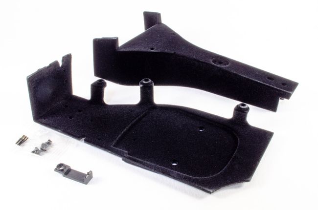 Some internal work I always find these a little hard to photograph as they are so black and have a velvet texture to them which can be easily marked with just touching. I find a piece of de-tacked tape is useful for removing any skin flakes or stray fibres/hairs from the surface. The two main sections are screwed together as shown and a cable clip fitted into position on the underside. 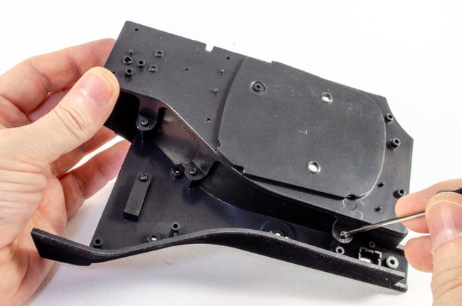 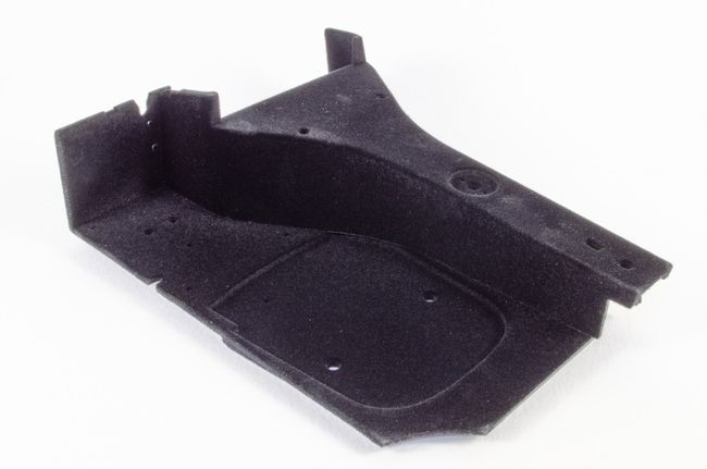 STAGE 44: RIGHT FLOOR SECTION AND FLOOR MATS STAGE 44: RIGHT FLOOR SECTION AND FLOOR MATS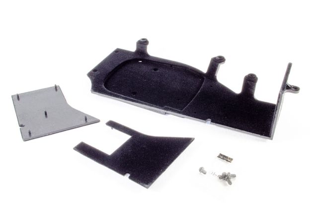 More delicate interior work now that I try so hard not to touch with my fingers! The passenger and driver floor mat just push neatly into position. 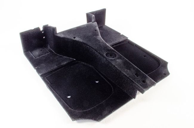 STAGE 45: COCKPIT REAR WALL STAGE 45: COCKPIT REAR WALL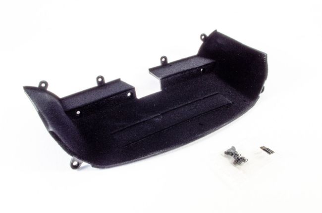 Same for the cockpit rear wall that is now carefully offered up to the cockpit interior and secured with four more screws. 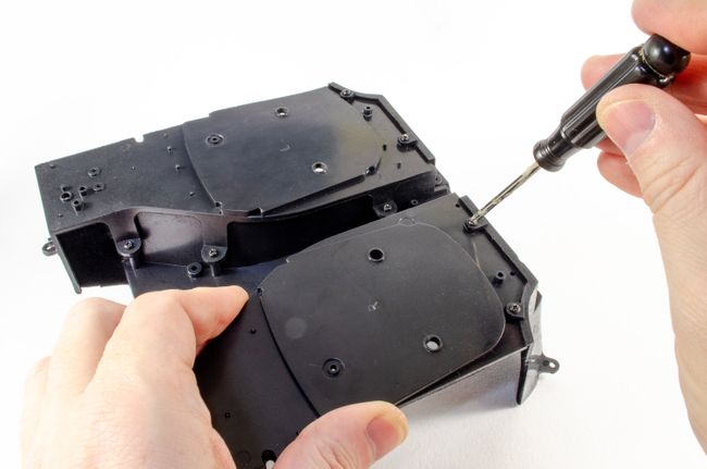 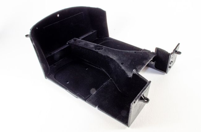 STAGE 46: GEAR LEVER, HANDBRAKE AND U-BAR STAGE 46: GEAR LEVER, HANDBRAKE AND U-BAR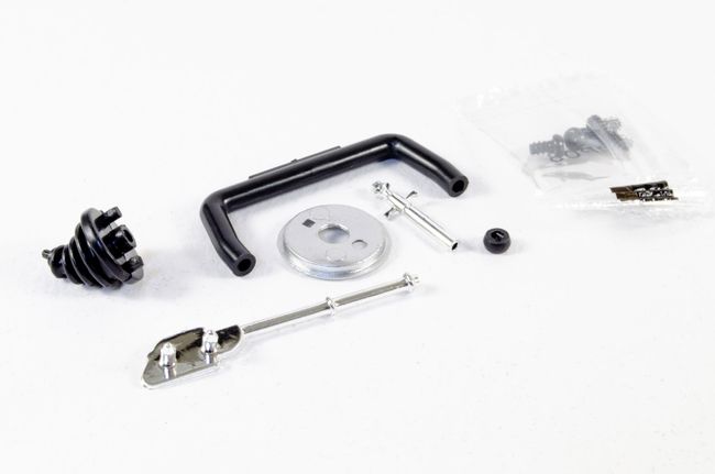 This simple pack adds the hand brake and gear levers, plus the console u-bar. The hand brake just pushes into the side of the interior while the remainder screw into place from underneath. 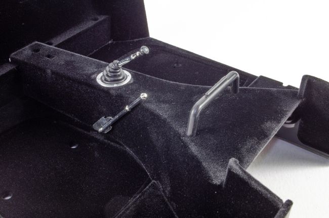 STAGE 47: ACCELERATOR PEDAL & SWITCH, BRAKE PEDAL & SWITCH, CLUTCH PEDAL, FLOOR PLATE STAGE 47: ACCELERATOR PEDAL & SWITCH, BRAKE PEDAL & SWITCH, CLUTCH PEDAL, FLOOR PLATE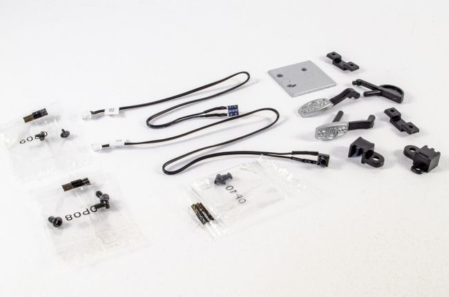 The pedal floor plate just pushes into position on top of the driver's floor mat, and then the accelerator, brake and clutch pedals are fitted as seen with screws from the reverse. 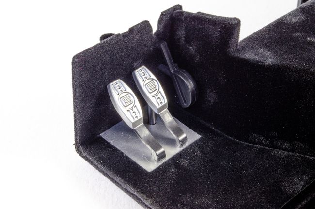 Microswitch assemblies are now fitted for two of the pedals. A switch is just pushed into a holder and the holder screwed to the cockpit reverse. A quick test of the switches with the pedals shows a positive action. No problems there! 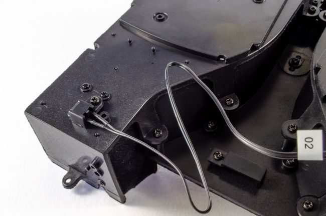 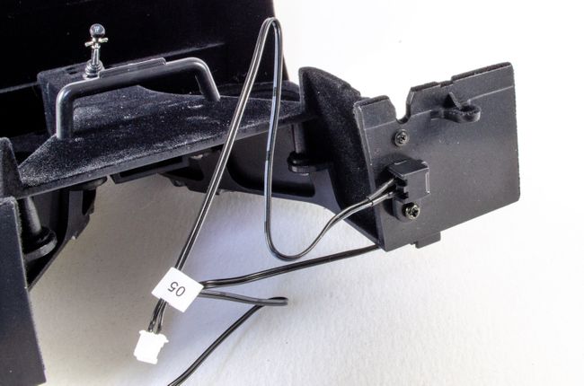 Cable management clips are now used to route the cables along the underside. 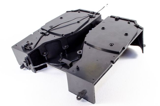 STAGE 48: MOUNTING BOX AND MAIN SWITCH STAGE 48: MOUNTING BOX AND MAIN SWITCH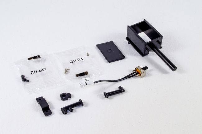 Another switch! This time a toggle for the car's on/off circuit. This pushes into place as seen here and a clip/screw used to secure it. The switch took a little effort to seat evenly. 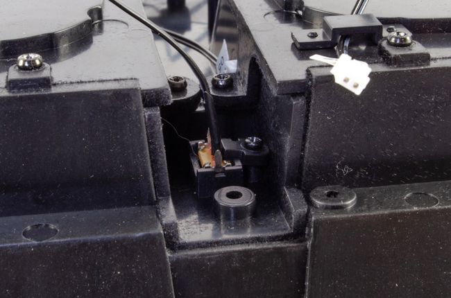 The mounting box is now fitted with pipes and the united screwed into position on the underside of the car. A little lid is also supplied. No surprise that this is where the batteries for the electronics will eventually fit. 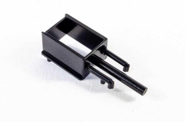 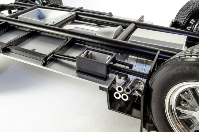 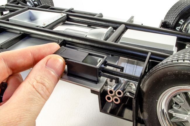 Last up is another cable management clip that helps to hold down the cable that I originally taped down for safety. 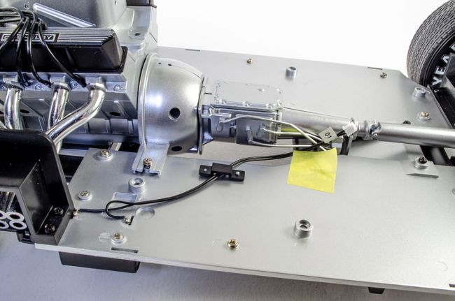 That's it for another month!
|
|
|
Rank: Semi-Pro Level 2 Groups: Registered
Joined: 11/01/2017 Posts: 89 Points: 259 Location: Lancashire, UK
|
Onwards with Pack 7! It really doesn't seem to have taken long to get to this stage. Quite a simple pack this month that concentrates on the interior, so we can 't yet cure the wobbly front wheels on the main chassis. 😜 I've put some stages of this pack in the same sequence as at least 3 stages contain zero work. STAGE 49 & 50: BUCKET SEAT/PASSENGER SEAT COVER, SEAT BELTS AND SEAT-BELT HARNESS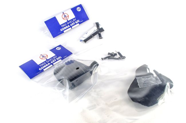 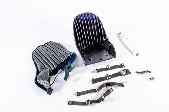 First up, the double-sided 3M tape is cut to size and stuck in position on the plastic seat, like this. I ignored the instruction to cut to 4 lengths the same size as you really need to cut them to the actual size needed. The front tape lengths are then trimmed to shape. 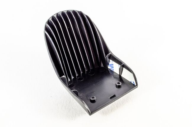 After peeing off the outer tape paper, the seat cover is slid over the plastic seat and then the sides pulled in so the tape fixes them in position. This is a little awkward, but works quite well. 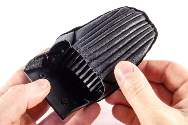 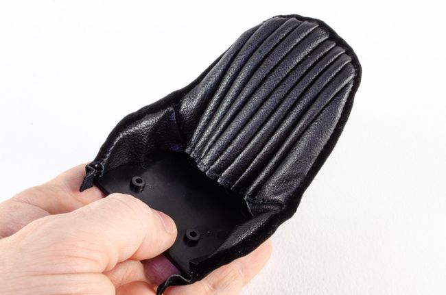 With the seat cover in place, the seat cushion from a previous pack is then screwed to this, holding everything in place. 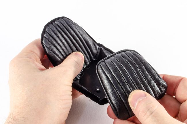 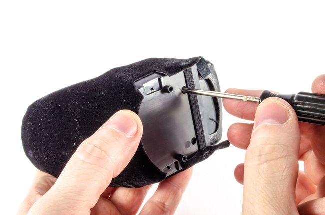 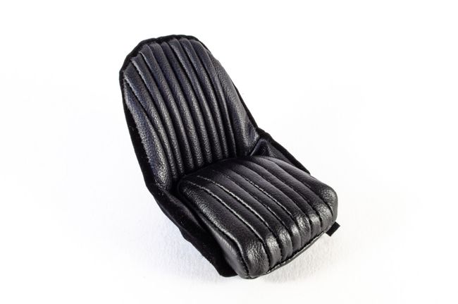 The lap belts are now pushed onto the lugs on the seat underside. These hold the parts real well, and I found no need to add any glue. 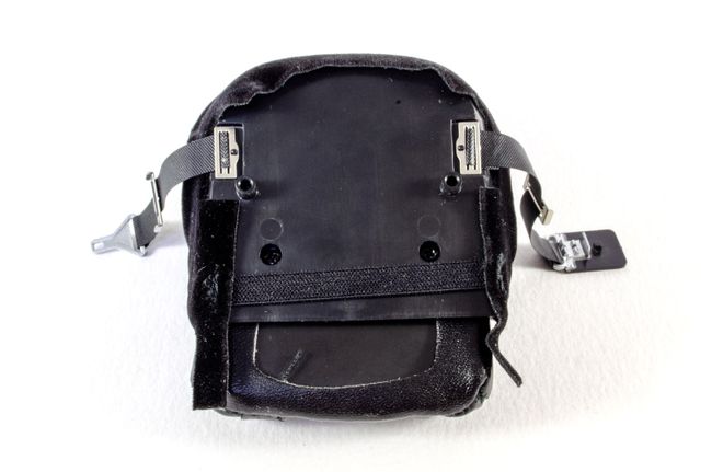 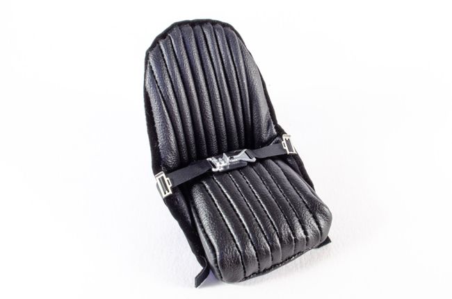 STAGE 51: BATTERIES, BATTERY CABLES & CUT-OFF SWITCH STAGE 51: BATTERIES, BATTERY CABLES & CUT-OFF SWITCH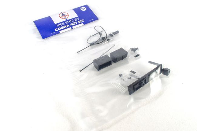 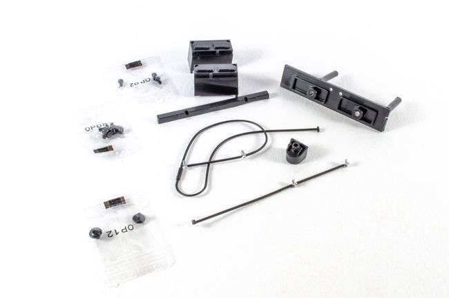 Both batteries are plugged onto the mounting unit. These can only fit one way. Two screws hold them in position. 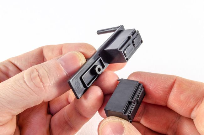 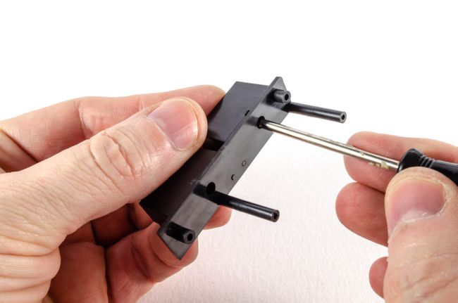 The battery unit is then screwed into position from the underside using 4 screws. 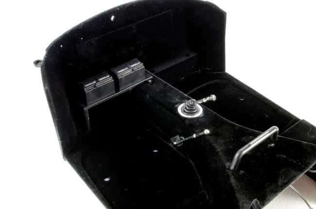 Both battery cables are then connected to the power shut off device, and this is then secured to the interior. 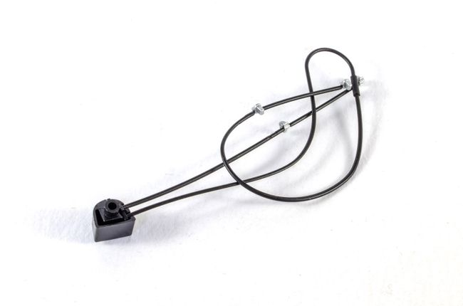 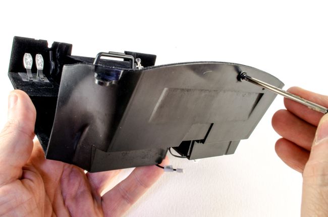 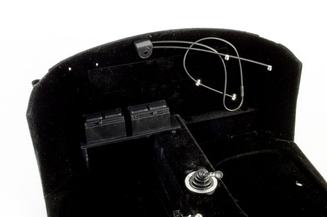 Both batteries are then 'wired up' like this. One cable will flap around, but that seems to be normal and it will be hidden behind a seat. Note I removed the gear stick too. That's to stop me damaging it. I'll replace it later in the build. 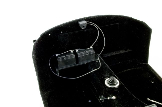 The battery holder is now pushed into place. No screws required. 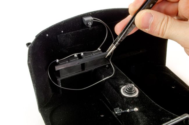 STAGE 52, 53, and 54: DRIVER BUCKET SEAT, DRIVER SEAT BOTTOM, DRIVER SEAT COVER, SEAT BELT AND SEAT-BELT HARNESS STAGE 52, 53, and 54: DRIVER BUCKET SEAT, DRIVER SEAT BOTTOM, DRIVER SEAT COVER, SEAT BELT AND SEAT-BELT HARNESS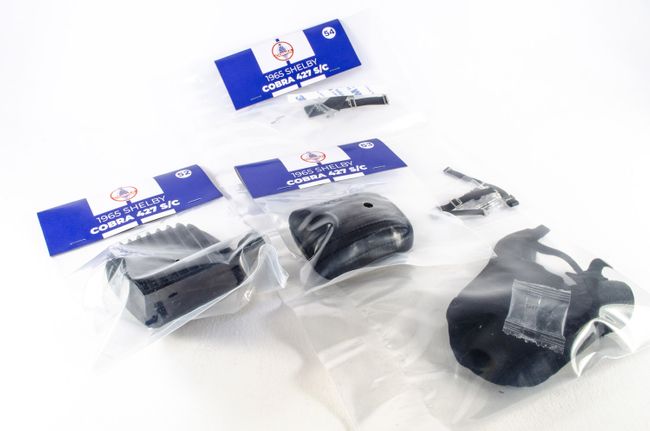 For the sake of repetition, the next seat is built up in the same way as the previous. 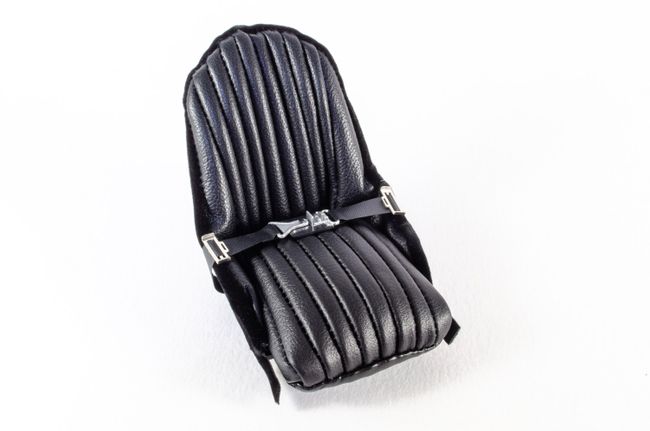 The two seat belt hooks are now pushed into position, and the belts fastened to them. 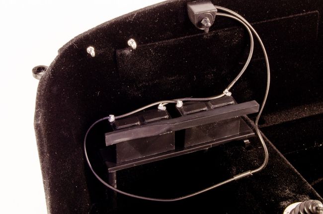 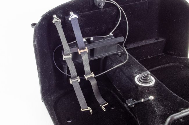 Both seats are now secured to the interior via screws from the underside. 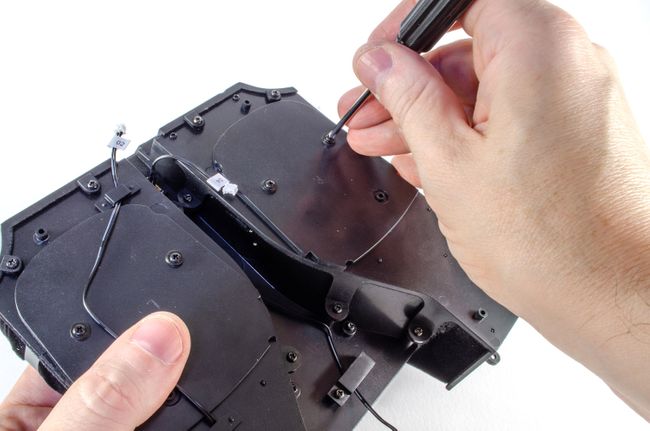 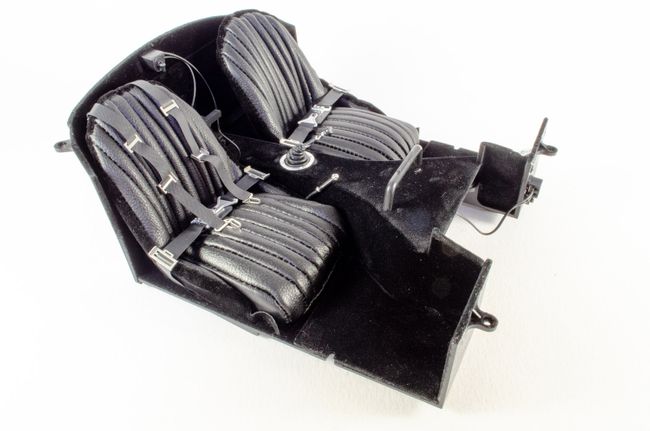 STAGE 55: TRUNK BOARD AND TANK FILLER PIPE STAGE 55: TRUNK BOARD AND TANK FILLER PIPE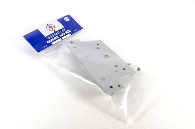 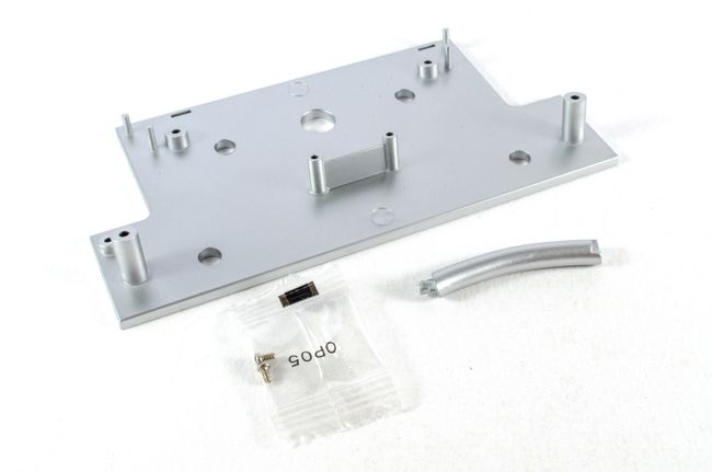 This one is dead simple. The tank filler pipe is secured to the truck board with a single screw. 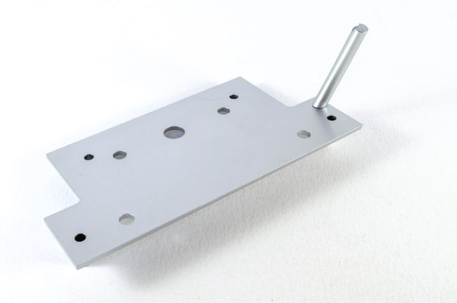 STAGE 56: CIRCUIT BOARD AND ELECTRICAL CABLES STAGE 56: CIRCUIT BOARD AND ELECTRICAL CABLES 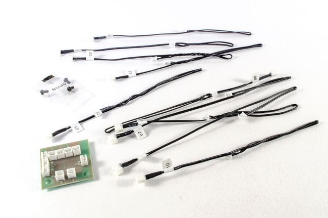 There's no actual electronics work involved with this, or testing. Each lead needs to be plugged into the socket on the circuit board that has the same number, When complete, the circuittboard is fastened to the trunk board. 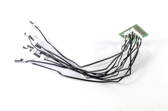 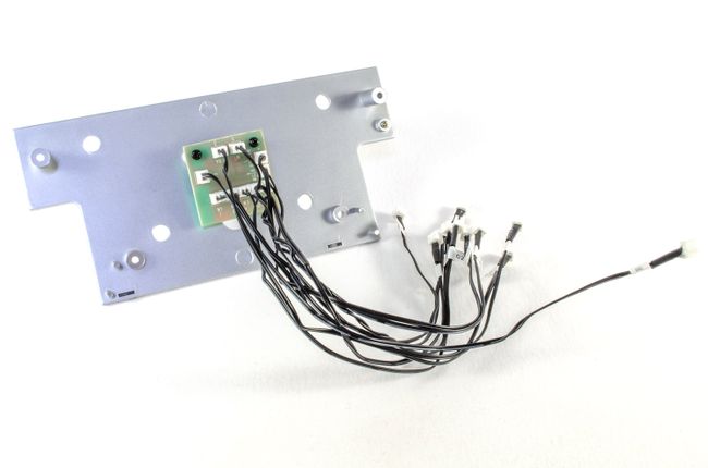
|
|
|
Rank: Administration Groups: Administrator, Administrators, Forum Support Team, Global Forum Support, Global Forum Support Team, Moderator, Official Builds Joined: 24/08/2009 Posts: 1,942 Points: 5,838 Location: UK
|
This is looking good! Is the pan flocked, or just textured? I’m modding mine into a straight comp car, so it’ll be aluminum.
I just got billed for the next pack, so I. About a month behind you.
Stay well,
Mark
|
|
|
Rank: Master  Groups: Registered
Joined: 25/03/2011 Posts: 1,027 Points: 3,075 Location: Lincolnshire
|
What a wonderful kit, real quality. You’re doing a fantastic job with it, keep those pictures coming Regards Glenn
|
|
|
Rank: Super-Elite Groups: Official Builds, Administrators, Moderator, Global Forum Support, Registered Joined: 04/06/2011 Posts: 5,610 Points: 16,982 Location: ipswich
|
A very impressive looking kit. I have no doubt that you are enjoying the build. Keep it coming - it's great following along.
|
|
|
Rank: Semi-Pro Level 2 Groups: Registered
Joined: 11/01/2017 Posts: 89 Points: 259 Location: Lancashire, UK
|
Pack 8This pack came together quite quickly, and didn't need the chassis at this time, so all work was a lot smaller and concentrated on the fuel tank and electronics, plus some cockpit elements. STAGE 57: FUEL TANK STAGE 58: REAR TRUNK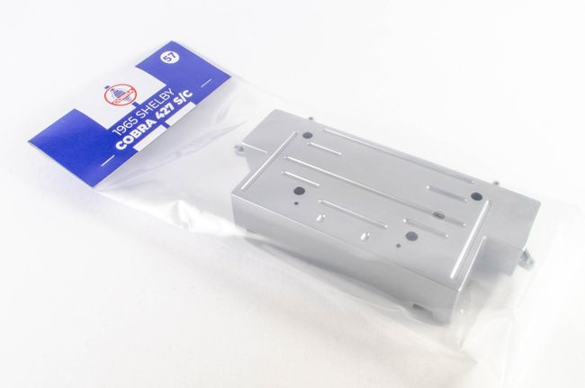 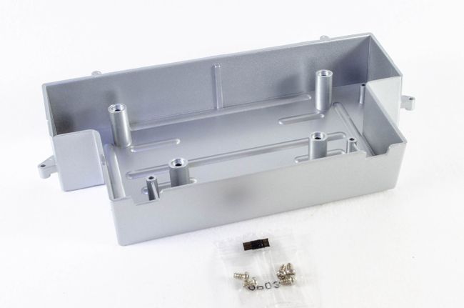 This is the main part of the fuel tank that we started earlier, and bolted the electronics into . Now we can complete the tank and route the cables appropriately. I just hope the boards all work well as there's no test for it before encasing inside the car. 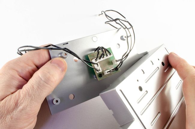 Specific cables pass through specific openings, and the whole assembly screw tightly shut. 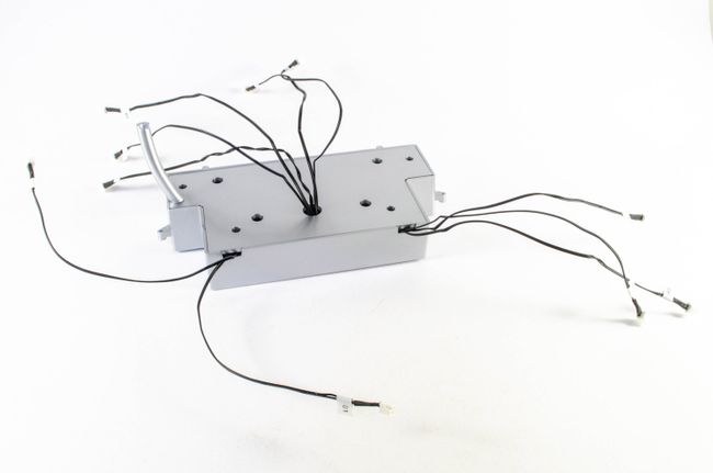 STAGE 58: REAR TRUNK STAGE 58: REAR TRUNK 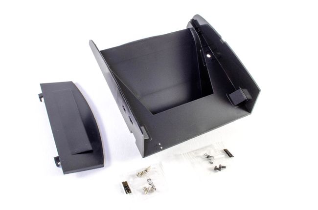 The boot, as we call it in the UK, is now tackled. The rear panel first screws to the main section. 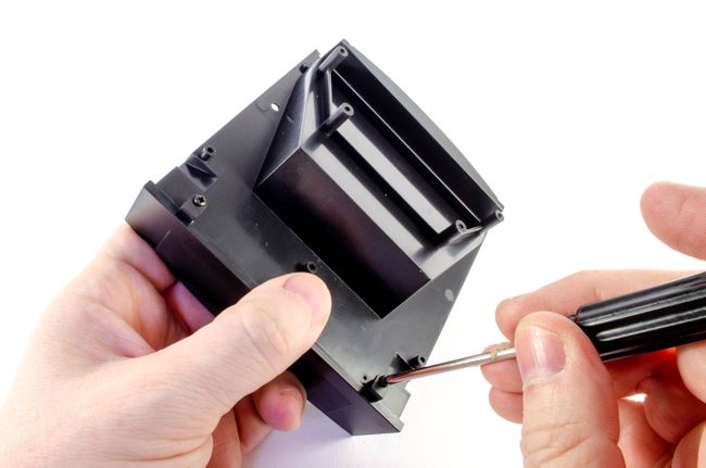 The completed fuel tank now bolts to the underside. Be careful no wires are trapped anywhere here. 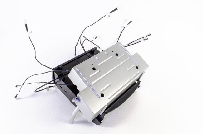 STAGE 59: FUEL PUMPS, PIPES, TRUNK HINGE & LOCK STAGE 59: FUEL PUMPS, PIPES, TRUNK HINGE & LOCK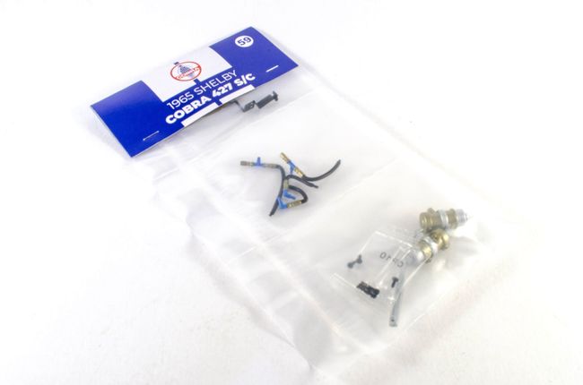 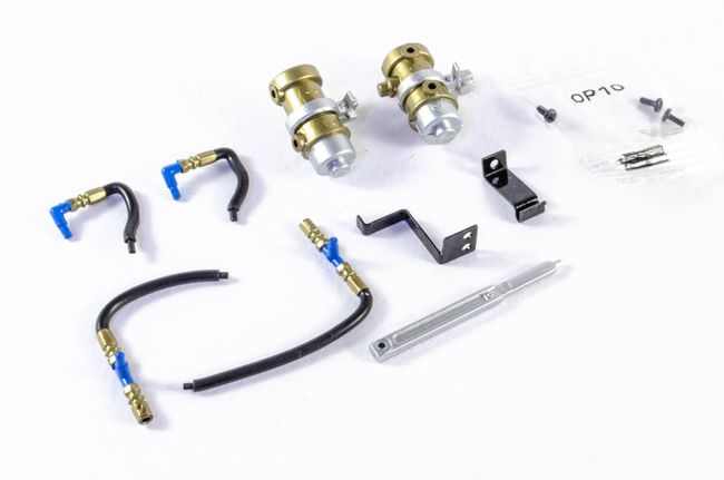 Trunk detail is now added with the two fuel pumps and their plumbing. This all fits superbly with too awkwardness, and exactly as shown. The pics in the instructions are quite small so it took a moment to fathom which pump was which. 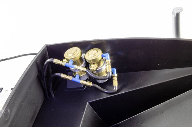 The true support is now fitted, albeit it drops off quite easily but think that will be sorted in a later issue. 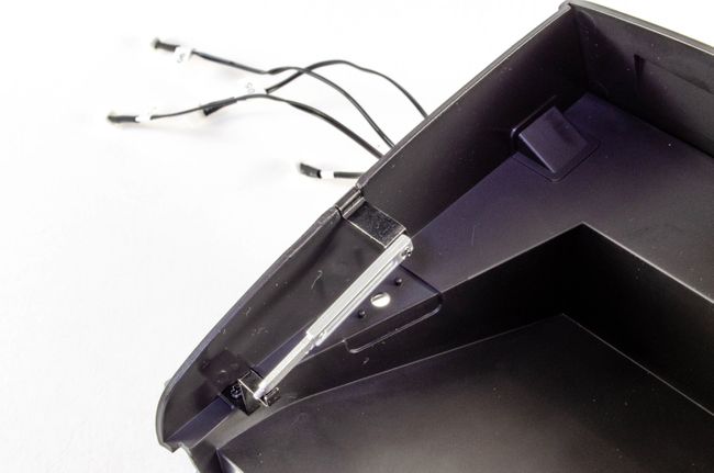 STAGE 60: REAR FENDER PART & CABLE HOLDER STAGE 60: REAR FENDER PART & CABLE HOLDER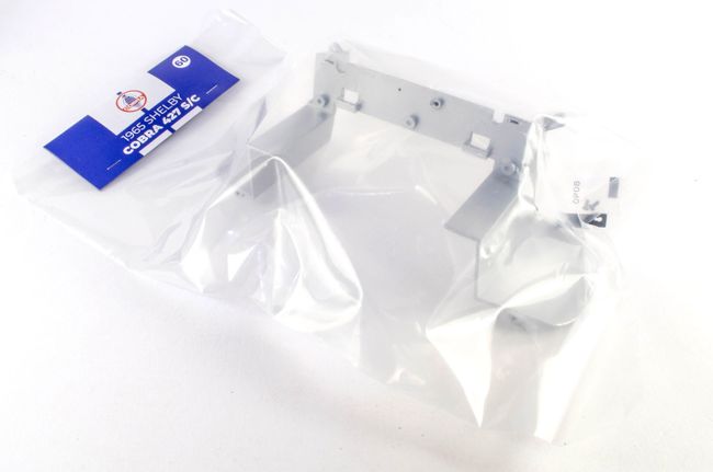 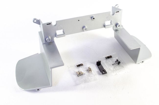 The rear fender is another large part and this now bolts to the tank and truck assembly after first threading the specific cables through the correct fender opening. 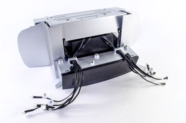 A cable clip is now used to channel all wiring into the same locale. 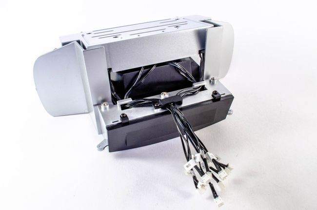 STAGE 61: FIREWALL STAGE 61: FIREWALL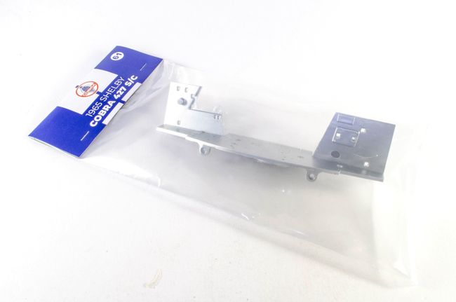 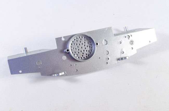 A nice looking part, but literally nothing to do until.... STAGE 62: SPEAKER AND SPEAKER HOLDER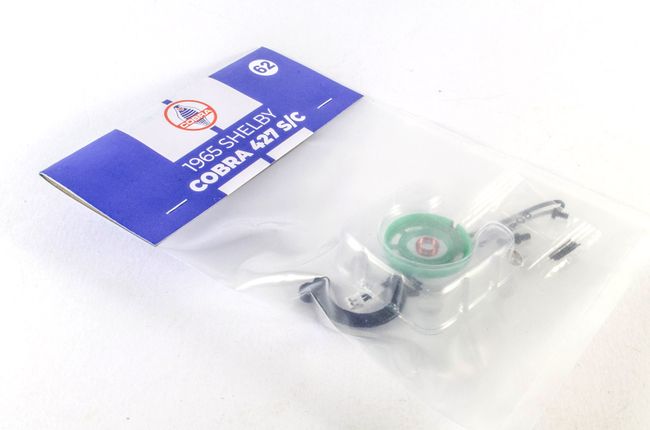 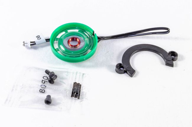 Now the firewall can be populated with components, but first, the speaker is installed. 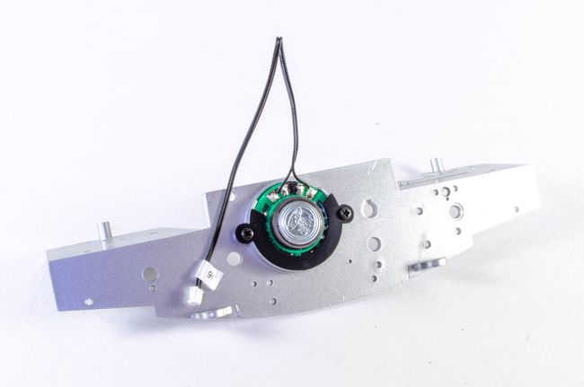 STAGE 63: CABLE HARNESS AND ELECTRICAL DEVICES STAGE 63: CABLE HARNESS AND ELECTRICAL DEVICES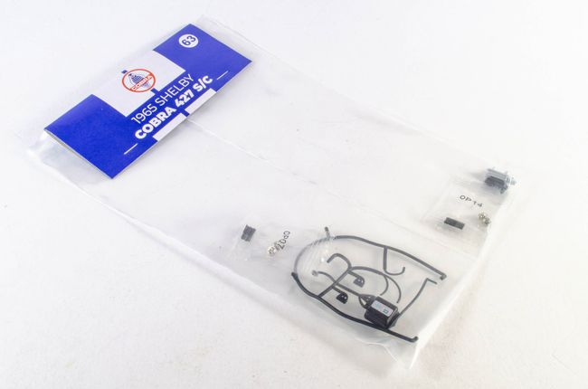 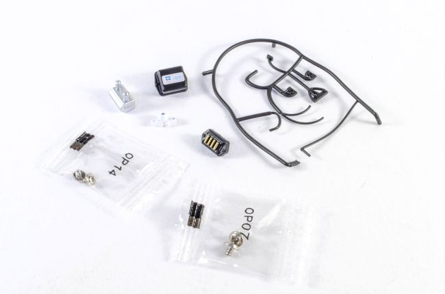 'Electrical devices' is a generic term for everything that bolts to the firewall. Note also a nicely moulded wiring harness. 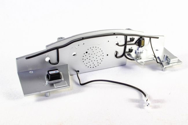 The harness is first plugged into the various holes, and then the electrical devices into position as shown, trapping the harness in places. STAGE 64: MORE ELECTRICAL DEVICES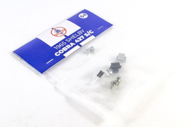 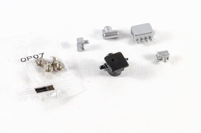 More 'electrical devices' to complete the firewall. 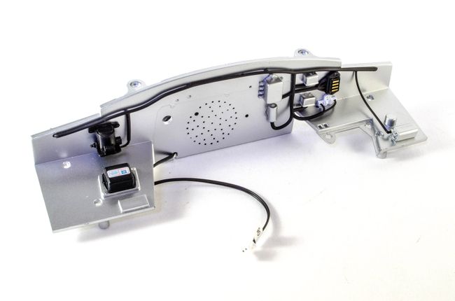 more soon!
|
|
|
Rank: Semi-Pro Level 2 Groups: Registered
Joined: 11/01/2017 Posts: 89 Points: 259 Location: Lancashire, UK
|
Pack 9Quite a bit of work in this pack and.....YES!!...we manage to get rid of that pesky front wheel sag on the main chassis, which has driven me mad for a couple of months now.
STAGE 65: DRIVER SEAT-BELT HARNESS, HOOKS & FRONT LATERAL CAGE RIGHT BAR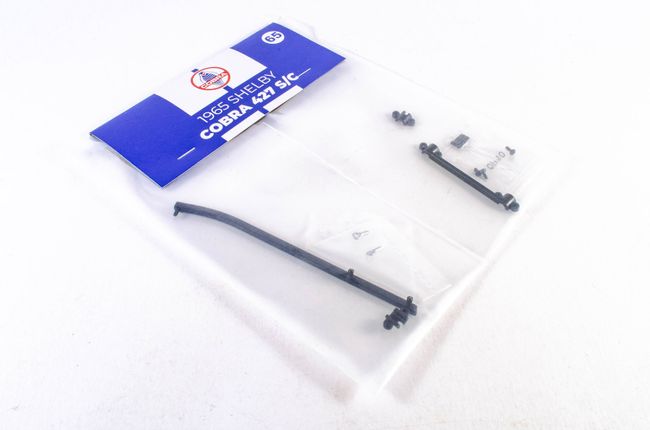 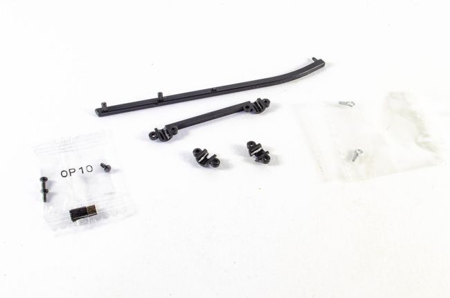 The u-shaped roll bar from an earlier pack is now resurrected and the belts are fastened to it. First, the bracket, then the harness hooks. 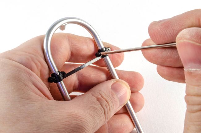 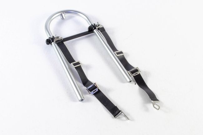 The right lateral cage bar is now pushed into place on the firewall. 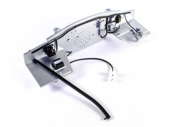 STAGE 66: OIL VAPOUR CANISTER, PIPES, CAP, & AIR INTAKE PIPE STAGE 66: OIL VAPOUR CANISTER, PIPES, CAP, & AIR INTAKE PIPE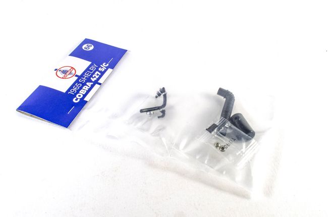 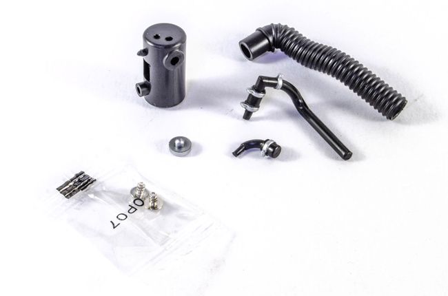 A few more detail bits for the firewall. First, the oil vapour canister is built and plugged into position. 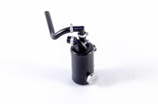 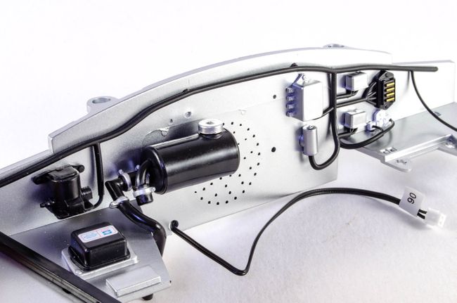 Now the air intake pipe is attached. 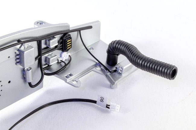 STAGE 67: STEERING SYSTEM SHAFT, CAM GEAR BRACKET & COVER STAGE 67: STEERING SYSTEM SHAFT, CAM GEAR BRACKET & COVER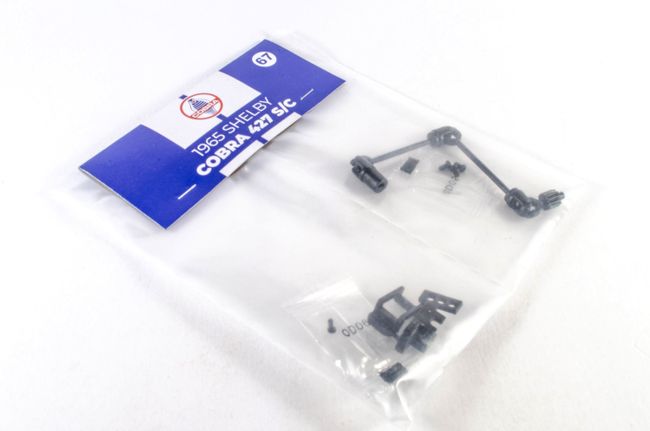 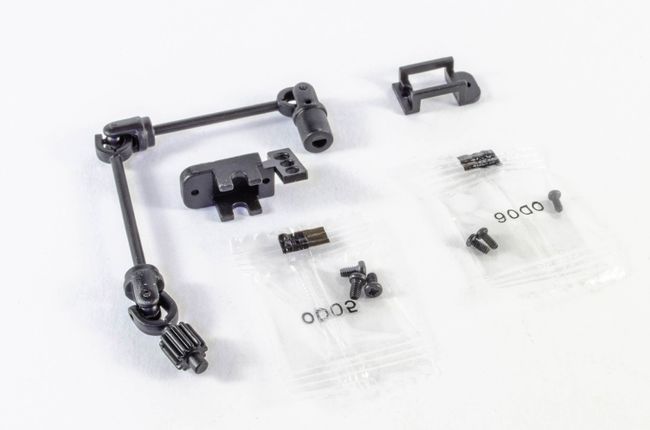 After screwing the cam gear bracket into place, the steering shaft can be threaded into position and secured in place. 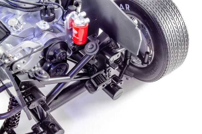 STAGE 68: STEERING ROD & COLUMN STAGE 68: STEERING ROD & COLUMN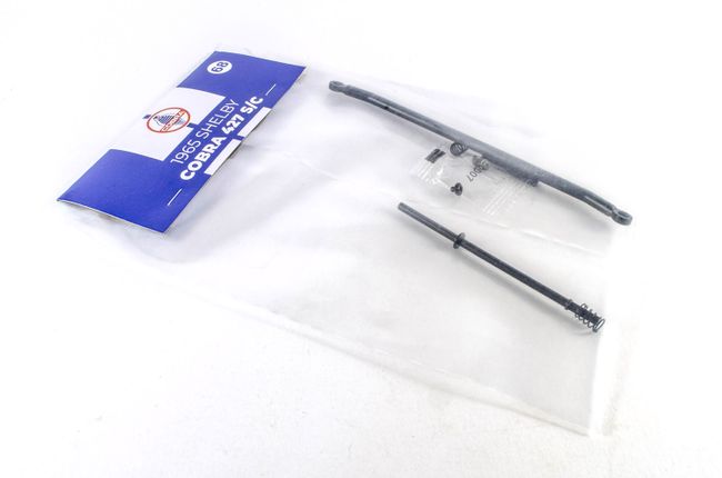 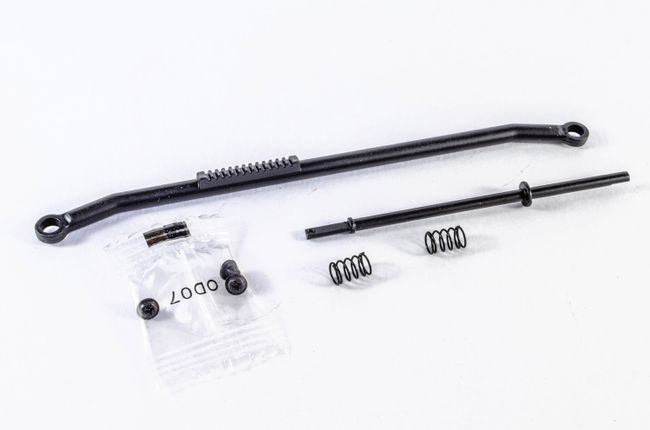 The steering column is first inserted through the rear of the instrument panel 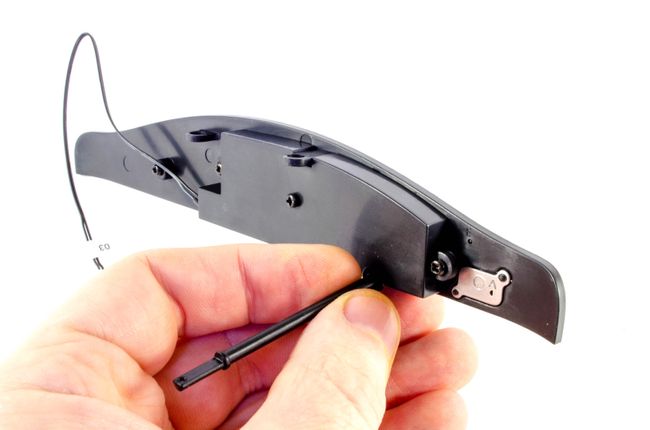 and the steering wheel pushed into place. This is quite a tight fit and quick tap with a rubber tipped model hammer drove it full home (no pun intended!) 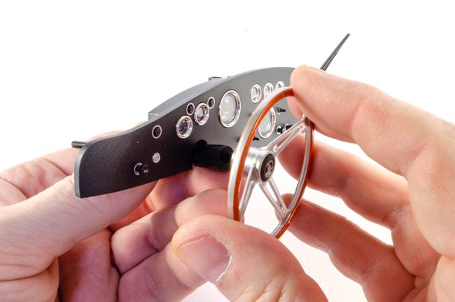 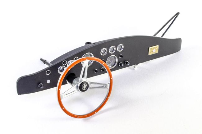 NOW we can get rid of the saggy front wheels! The springs are first slid onto the hub tubes and then the wheels aligned. The steering rod is then pushed into position on the seat and fastened at both sides on top of the springs. No more saggy wheels 🙂 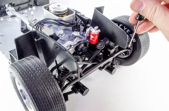 STAGE 69: TRUNK, EMBLEM & LICENSE PLATE LIGHT STAGE 69: TRUNK, EMBLEM & LICENSE PLATE LIGHT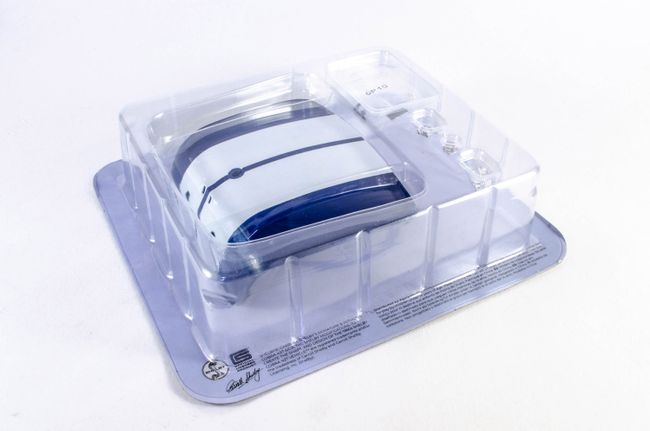 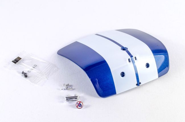 The emblem is screwed into place and the latch and license plate light are pushed into position. 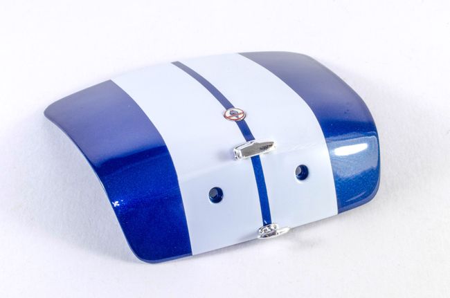 STAGE 70: TRUNK HINGES, BRACKET, & REAR LICENSE PLATE STAGE 70: TRUNK HINGES, BRACKET, & REAR LICENSE PLATE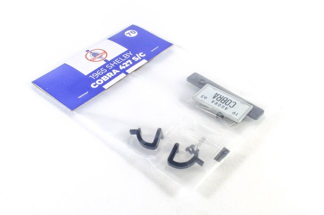 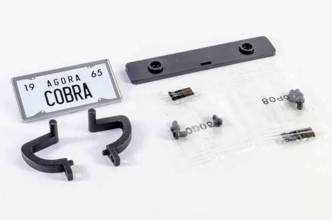 Now the trunk hinges are fitted. 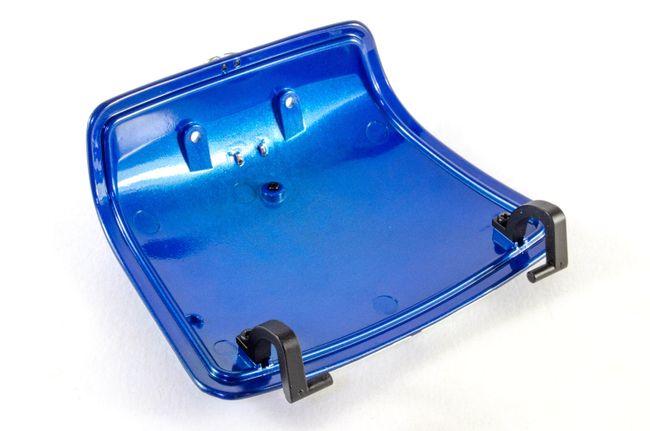 Followed by the license plate, screwed into place from behind. 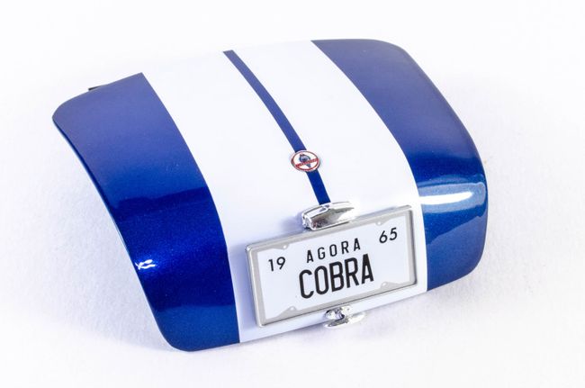 STAGE 71: LEFT DOOR, TRIM & RIVETS STAGE 71: LEFT DOOR, TRIM & RIVETS 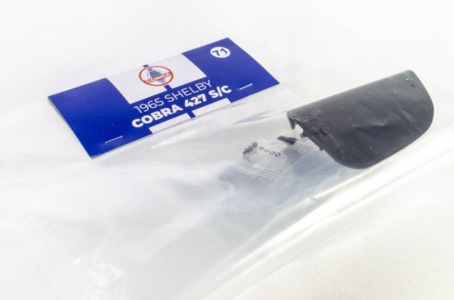 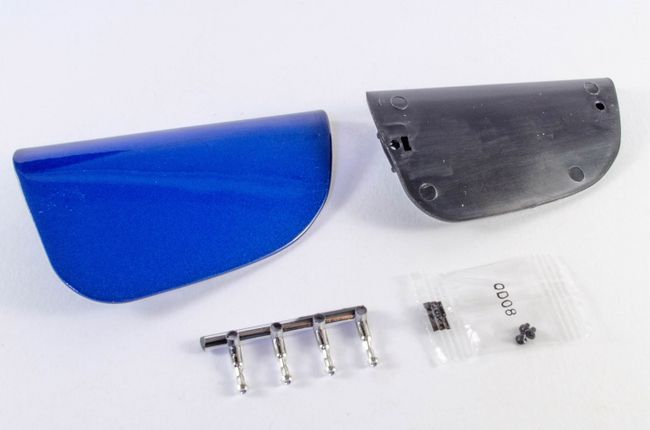 The left door trim is screwed into the interior of the left door. 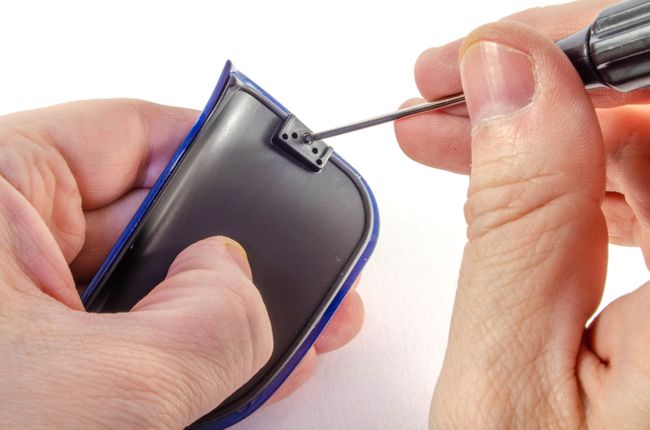 The door top rivets are then shipped from their sprue and pushed into place as shown. 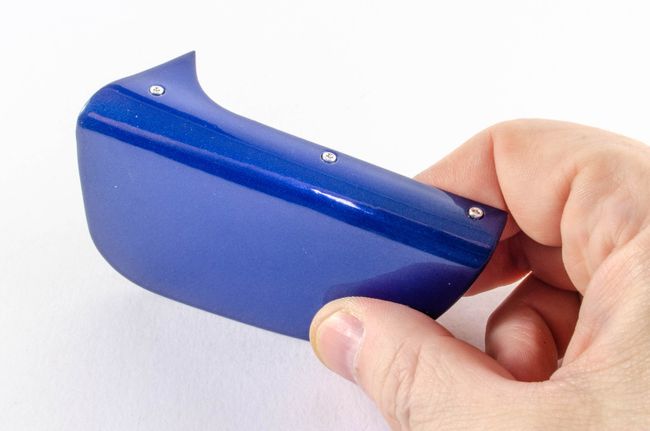 STAGE 72: LEFT DOOR HINGE AND LOCK STAGE 72: LEFT DOOR HINGE AND LOCK 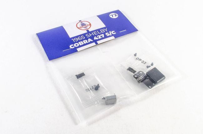 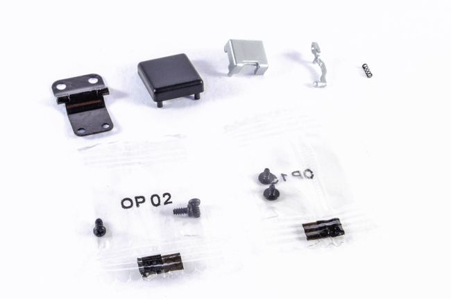 A little fiddly this one, but goes together nicely. The spring is slid onto the lock handle and then the assembly is screwed into the mechanism. Don't tighten too much or the lock won't move. 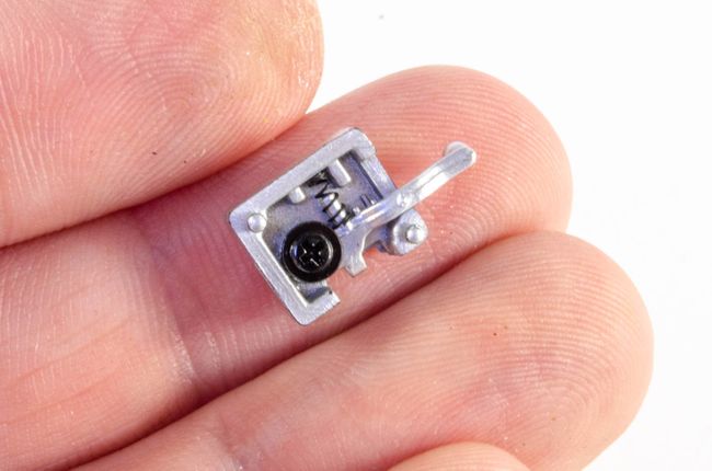 The door hinge is now screwed into place. 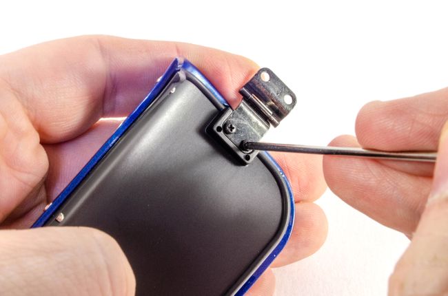 And the lock mechanism and hinge cover are pushed into place. 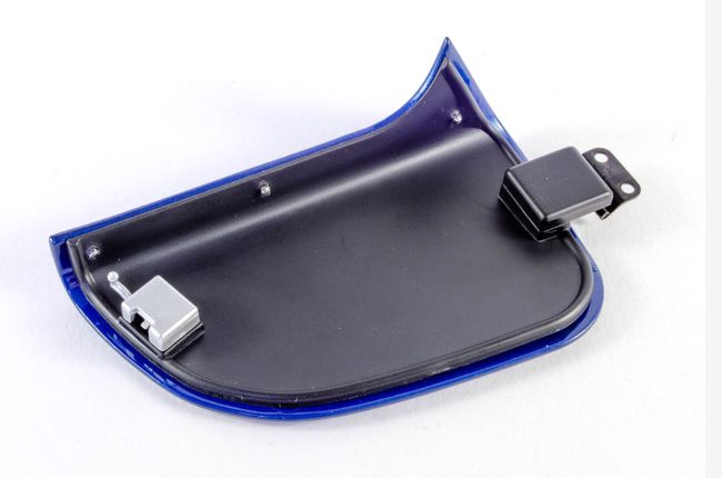 STAGE 73: RIGHT DOOR, TRIM & RIVETS STAGE 73: RIGHT DOOR, TRIM & RIVETS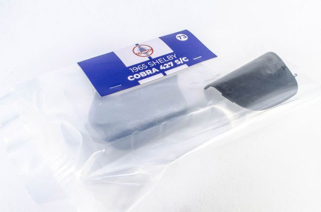 This one simply builds up the right door as per the left. 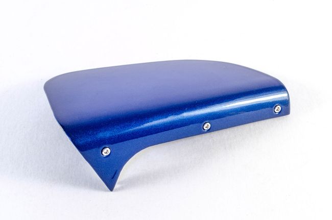 Until pack 10, see you soon!
|
|
|
|
Guest (2)
|
 US
US

